Pianno effect

to3metalcan

Joined Jul 20, 2014
263
ghebaur, quick question - are you confused about positive and negative voltage? Op amps are traditionally run on two DC supplies...one is more positive than 0V (ground.) The other is more negative than 0V(ground.) The inputs and outputs of the op amps can then be at 0V, which means you don't need capacitors to connect them to other circuits (in most situations.) By using a coupling capacitor and a voltage divider, you're basically "tricking" the op amp into treating 4.5V as ground, which makes it act as though it has a +4.5V supply and a -4.5V supply (the voltages of hot and actual ground compared to 4.5V.) But to another circuit, that 4.5V doesn't look like ground...it just looks like 4.5V! So you use capacitors to keep the DC voltage inside the circuit.

You can set up +/-9V by connecting two batteries together. It works pretty well, but sometimes the batteries don't age at the same rate and you end up with a ground that isn't actually halfway between the rails, which will make your output clip weirdly.
 

Veracohr

Joined Jan 3, 2011
783
Am I missing something, or does the second stage (the lowpass stage) have no DC bias with the schematic as shown?
Oops, I actually meant to take C4 out of the schematic. U2 doesn't need to be biased at the midpoint because the output of U1 already is. U3, on the other hand, needs biasing because the HP structure puts the caps in series.

If the final plan isn't to sum the stereo signal to mono, then U1 wouldn't need to be there and U2 would need to be biased.
 

Thread Starter

ghebaur

Joined Jun 17, 2014
35
I tested the LP filter using my old LM324. I got nothing, probably the opamp it's broken. When the opamp is powered i get some buzzing and a small attenuation alongside the original audio input and when is not powered there's no more buzzing.

Anyways, i hope i can get my hands on some brand new opamps soon.


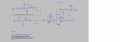
I just tested the circuit in LTspice using my wav file as input. So i have LP ->HP->Distortion->Attenuation. All the stages work as they should when i do AC Analysis but when i do Transient analysis and output wav files to hear how it works i have a problem. The first three stages work as they should but after the Attenuation stage the clipping and distortion disappears and i'm left only with the LP+HP filter and a small gain.

If i build the circuit physically will i get the same result? (I attached the circuit i built).
 

Attachments

Last edited:

Thread Starter

ghebaur

Joined Jun 17, 2014
35
I believe the the circuit will act the same way in real life. Still, the question remains. How do i make clipping to obtain the desired result?
 

Thread Starter

ghebaur

Joined Jun 17, 2014
35
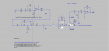
I'v been doing some research and i found out that clipping can be made using diodes. Thy do the job, i get clipping but the problem is that i don't get the sound i want.


What other Spice program do you use? I don't really like LTSpice.
 

Attachments

to3metalcan

Joined Jul 20, 2014
263
Wait, now we're talking about two different schematics. Is the only difference in this one the clipping diodes?

Assuming the answer is "yes," I think you might be seeing a simulation artifact...a stage cannot magically "un-clip" the previous stage's clipped output (how would it know what the signal looked like before?) Attenuate it all you want...it's still going to be a quieter version of the clipped output.

Next, your overdrive stage is totally excessive... The bandwidth of a real op-amp at that gain will be severely limited, and the 10meg resistor will be noisy as heck...this stage may output noticable amounts of white noise. Try two successive gain stages that multiply out to the gain you need.
 
Last edited:

Thread Starter

ghebaur

Joined Jun 17, 2014
35
Wait, now we're talking about two different schematics. Is the only difference in this one the clipping diodes?

Assuming the answer is "yes," I think you might be seeing a simulation artifact...a stage cannot magically "un-clip" the previous stage's clipped output (how would it know what the signal looked like before?) Attenuate it all you want...it's still going to be a quieter version of the clipped output.

Next, your overdrive stage is totally excessive... The bandwidth of a real op-amp at that gain will be severely limited, and the 10meg resistor will be noisy as heck...this stage may output noticable amounts of white noise. Try two successive gain stages that multiply out to the gain you need.

Basically the main difference is the clipping diodes.

So, i don't need the two diodes to clipp the signal? Thea amplifier clipps the signal?
 

to3metalcan

Joined Jul 20, 2014
263
If you have clipped output at the point marked "distort" sans clipping diodes, nothing that happens after that can turn it back into un-clipped output. The reason diodes are preferred in a lot of cases is because they're going to clip at the same low, predictable level regardless of the voltage rails, whereas the op amp has to drive the signal all the way up to the limits of the power supply. That said, before you give up on clipping diodes, try two of em in a row in each direction, or two in one direction and one in the other...sometimes asymmetric clipping is much more interesting sounding. For that matter, you can try three and two, or whatever!
 

Thread Starter

ghebaur

Joined Jun 17, 2014
35
If you have clipped output at the point marked "distort" sans clipping diodes, nothing that happens after that can turn it back into un-clipped output. The reason diodes are preferred in a lot of cases is because they're going to clip at the same low, predictable level regardless of the voltage rails, whereas the op amp has to drive the signal all the way up to the limits of the power supply. That said, before you give up on clipping diodes, try two of em in a row in each direction, or two in one direction and one in the other...sometimes asymmetric clipping is much more interesting sounding. For that matter, you can try three and two, or whatever!

I did tried different combinations for symmetrical and asymmetrical clipping, and this is setup is the one i like most. I'll keep tweaking till i get an acceptable result. I replaced R7 with 10kΩ and R5 with 10.
 

bertus

Joined Apr 5, 2008
23,005
Hello,

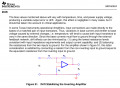
Here is a bit of more info on the R3 in your schematic:


This comes from the attached PDF, on page 45.

I also see that you are using the LM324 as an opamp.
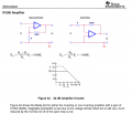
When you have a amplification of about 500, the bandwidth will be 1MHz / 500 = 2 kHz.
Above this 2 kHz the signal will go down with 20 dB / Decade.

Here is an example of a 1000X amplifier from the same PDF:


This is found on page 38.

Bertus
 

Attachments

Last edited:

Thread Starter

ghebaur

Joined Jun 17, 2014
35
Hello!

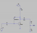
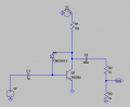
I'v built this simpler circuit(fuzz effect) physically using a schematic i found on internet and i have a problem. Despite the fact that i turn the volume knob of my audio system to maximum there is no change in the volume... The volume stays at the same level, is as lawd a normal person talking.

Probably i should add something or remove something from the schematics...
 

Attachments

Thread Starter

ghebaur

Joined Jun 17, 2014
35
I believe this was the original schematic http://www.diyguitarpedals.com.au/shop/boms/7_Min_Fuzz_Schematic.pdf.


Now i see it was 10k instead of 150k. I'll replace that ASAP.

LE: I made some changes and it WORKS!!!! Thank you a lot bertus, i was about to throw it on the window.
It's funny to see how only power chords sound nice and "clean" with this effect, every other chord sounds like crap.
 

Attachments

Last edited:

bertus

Joined Apr 5, 2008
23,005
Hello,

What happens when you remove R3 and short R2?
This is the maximum you can get from the circuit.
In the original schematic a potentiometer of 100K is used.

Bertus
 
Top