Photodiode equivalent circuit with transimpedance amplifier

Thread Starter

otters

Joined Jul 17, 2024
11
1721204319499.png

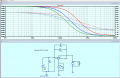
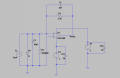
Hello please help me! I am having trouble getting values for the equivalent circuit of a photodiode in zero bias. Lets say I would like to model this after the BPW34 photodiode, what commercially available values should I use for the capacitor and shunt resistance? And what diode should I use? The datasheet does not state the shunt resistance. Thank you!!
 

Attachments

Thread Starter

otters

Joined Jul 17, 2024
11
Hi thanks for replying! Unfortunately I am unable to upload the asc file as the file location of the OPA380 i uploaded into the LTSpice is from my personal files and unauthorized personnel are unable to access it. Here is the file with a universal opamp instead
 

Attachments

Last edited:

Thread Starter

otters

Joined Jul 17, 2024
11
Hi otters.
In this .lib file look at Line #258
Use your Text editor to open and read it.

Let me know if you have a problem.
E
Thank you!!! so according to the model parameters, capacitance should be 72pF. However, I dont see a value for shunt resistance as well as which diode I should use.
 

ericgibbs

Joined Jan 29, 2010
21,390
Hi otters.
Also check out this Vishay BPW34 PDF
E

Clip:
RS, and shunt resistance, Rsh, representing an additional leakage) can be neglected in most standard applications, and are not expressed in equations 5 and 7
 

Attachments

Last edited:

Thread Starter

otters

Joined Jul 17, 2024
11
Hi otters,
Look at this link showing the equivalent circuit.
I would be interested in seeing your final asc file.

E
https://blog.mbedded.ninja/electronics/components/diodes/photodiodes/

View attachment 327144
thank you!! I see that this blog you sent me stated that the diode should be an ideal diode. isit possible to use a commercially available diode as I would need to simulate this circuit in real life in order to control the current as there is a photodiode prototype that will take its place eventually. Or is there any other way to control the photocurrent generated? the series resistance value stated in the Spice model is 0.1ohms. Will it be ok to ignore this resistor as when this resistor is added, the circuit becomes an inverting configuration instead of a transimpedance amplifier configuration and the gain will factor in this small resistor.
 

ericgibbs

Joined Jan 29, 2010
21,390
Spice model is 0.1ohms. Will it be ok to ignore this resistor as when this resistor is added, the circuit becomes an inverting configuration
Hi,
I would ignore a 0.1R series resistance value.
Redraw your LTSpice file and post a copy, let's see how it performs.
E
 

tonyStewart

Joined May 8, 2012
231
Can quantify what optical quality you want to detect ? I need brightness wavelength and speed.

This may be done much better than what you posted.
 

Thread Starter

otters

Joined Jul 17, 2024
11
Can quantify what optical quality you want to detect ? I need brightness wavelength and speed.

This may be done much better than what you posted.

Hi! Im trying to detect light under various conditions, up to 1 sun (1000W/m2), with a solar simulator. Wavelength is visible light, around 380nm to 700nm
 

tonyStewart

Joined May 8, 2012
231
Hi! Im trying to detect light under various conditions, up to 1 sun (1000W/m2), with a solar simulator. Wavelength is visible light, around 380nm to 700nm
That’s easy but how about using a log scale eye corrected spectrum over 5 decades using a single 5V LDO?
What viewing angle?
 

Thread Starter

otters

Joined Jul 17, 2024
11
That’s easy but how about using a log scale eye corrected spectrum over 5 decades using a single 5V LDO?
What viewing angle?
Thank you for the suggestion! For the viewing angle the photodiode will be placed in a watch, hence the viewing angle is not constant. I think the suggested circuit will be a better option for my current project. I will research more and post another schematic soon!
 

Thread Starter

otters

Joined Jul 17, 2024
11
I need help with another issue. Are my capacitor values too large? I am unsure on how to properly calculate the feedback capacitor

1721293848448.png
 

tonyStewart

Joined May 8, 2012
231
Using negative feedback (NFB) with a single supply, you should have the anode grounded instead with a negative input cancelled by a positive output. You may use any yellow, red or IR chip LED to test your circuit. There is no need for capacitors unless you want them. All diodes have C (pF). F=1/(2pi RC)
 
Last edited:
Top