 Facebook
 Google
 GitHub
 Linkedin
Hi there,
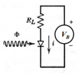
I am an EE student studying for an upcoming final. My question pertains to a very simple circuit containing a resistor, a voltage source, and a photodiode.
The photodiode is receiving an input intensity of 500 mW/m^2. The PD has a responsivity of 0.4 A/W. The detector area is 1 mm^2. The load resistor we'll call 100 0hms. See image.
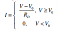
We're going to model the PD IV curve with a simple piecewise linear function, see image. Rd we'll call 10 ohms and V0 we'll call 0.5 A.
If I make the bias voltage so that the photodiode is in reverse mode, say Vb = -5V, what current am I going to see in the circuit? How can I figure this out? Please explain thoroughly because I am confused.
Cheers
Corwin S
I am an EE student studying for an upcoming final. My question pertains to a very simple circuit containing a resistor, a voltage source, and a photodiode.
The photodiode is receiving an input intensity of 500 mW/m^2. The PD has a responsivity of 0.4 A/W. The detector area is 1 mm^2. The load resistor we'll call 100 0hms. See image.
We're going to model the PD IV curve with a simple piecewise linear function, see image. Rd we'll call 10 ohms and V0 we'll call 0.5 A.
If I make the bias voltage so that the photodiode is in reverse mode, say Vb = -5V, what current am I going to see in the circuit? How can I figure this out? Please explain thoroughly because I am confused.
Cheers
Corwin S
Attachments
-
 17.6 KB Views: 13
 -
 3.4 KB Views: 13
Last edited:


