 Facebook
 Google
 GitHub
 Linkedin
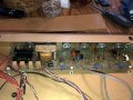
Hello everyone I have an old vintage 1975 peavey pacer 100 (45w solid state amp). I am fixing for a friend of mine. Back in summer 2020 it went dead. I replaced all the electrolytic caps and two of output power transistors, used deoxit on all the pots. It worked great after the 1st repair. Now it won’t go into overdrive crunch with the master volume gain knobs. My friend said he can still get distorted sounds with his pedal
board connected thru the input jack
I am thinking maybe one of the output power transistors are fried. The reason for this maybe is because I recall not getting a matched pair perhaps. I am also wondering if I did not apply the heat sink grease correctly. It uses mica insulators that are sandwiched between the chassis. Here is a link to a schematic and some pictures https://www.audioservicemanuals.com/pdf-download.php.
Attachments
-
 2.5 MB Views: 9
 -
 1.3 MB Views: 8
 -
 1.7 MB Views: 8


