Facebook
 Google
 GitHub
 Linkedin
Thank you for the explanations in this thread and also the derivations
I have managed to get to grips with how to derive an expression for I(t) and then finding the maximum.
Really my goal is now to justify that if both the peak current and voltage swing are known, R=V/I can approximate small changes (mOhm level) in the resistance in the circuit.
This is what I was really doing - trying to get an expression for the peak current so that I could justify removing I and C and just using R=V/I
I now seem to understand that this is more-so the case when the circuit is overdamped. What is the explanation for why when the circuit is overdamped that the inductance has little influence on the peak current so that you can approximate it with V=IR? Obviously it is something to do with the damping factor.
In fact the trouble I had explaining some real life measurements I think was due to the fact that some of my configurations were underdamped and using R=V/I isn't that accurate in this case. I have to make sure all my circuits have low inductance.
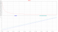
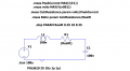
Here I have attached simulation of an RLC circuit
I have also plotted the real resistance in the circuit, as well as the 'calcresistance' where I have estimated it by dividing the voltage by the peak current (V=IR ohms law).
I have also plotted the 'ratio' between these
As we can see, when the resistance is small (circuit underdamped), my calcresistance using V=IR is several times the actual resistance in the circuit. However as the resistance increases (circuit overdamped) this ratio tends closer and closer to 1
Really I need to find a concise explanation for this.
I have managed to get to grips with how to derive an expression for I(t) and then finding the maximum.
Really my goal is now to justify that if both the peak current and voltage swing are known, R=V/I can approximate small changes (mOhm level) in the resistance in the circuit.
This is what I was really doing - trying to get an expression for the peak current so that I could justify removing I and C and just using R=V/I
I now seem to understand that this is more-so the case when the circuit is overdamped. What is the explanation for why when the circuit is overdamped that the inductance has little influence on the peak current so that you can approximate it with V=IR? Obviously it is something to do with the damping factor.
In fact the trouble I had explaining some real life measurements I think was due to the fact that some of my configurations were underdamped and using R=V/I isn't that accurate in this case. I have to make sure all my circuits have low inductance.
Here I have attached simulation of an RLC circuit
I have also plotted the real resistance in the circuit, as well as the 'calcresistance' where I have estimated it by dividing the voltage by the peak current (V=IR ohms law).
I have also plotted the 'ratio' between these
As we can see, when the resistance is small (circuit underdamped), my calcresistance using V=IR is several times the actual resistance in the circuit. However as the resistance increases (circuit overdamped) this ratio tends closer and closer to 1
Really I need to find a concise explanation for this.
Attachments
-
 26.6 KB Views: 20
 -
 26.4 KB Views: 19