Peak current in RLC circuit charging a capacitor

Thread Starter

Bakez

Joined Aug 21, 2012
31
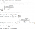
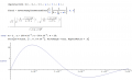
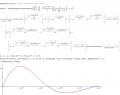
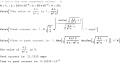
If I have a DC voltage source charging a capacitor, can anyone guide me how to derive a formula for the peak inrush current into the capacitor?

I have made a peak detector circuit that detects the peak current when charging 10nF-1uF capacitors and would like to have some theory to explain changes in the peak that I can see in real life


Thread Starter

Bakez

Joined Aug 21, 2012
31
Yes I know what they are and I know that larger inductance = lower peak current, higher capacitance = higher peak current etc

But I do not know the specifics
 

dl324

Joined Mar 30, 2015
18,362
You can calculate the peak current using the formula for charging a capacitor.

As for your non-ideal observations, in addition to the parasitics already mentioned; have you considered component tolerance?
 

crutschow

Joined Mar 14, 2008
38,537
You can do a simple calculation to find the peak inductor current without using calculus if you ignore the series resistance and look at the energy in the circuit:

It is known that an ideal series LC resonant charging circuit will have a peak voltage on the capacitor, Vc of twice the applied source voltage, Vs.
The peak capacitor energy is 1/2 CVc^2. For Vc = 2Vs E = 1/2 C(2Vs)^2 = 2CVs^2.

Since resonant charging results from the total inductor energy being transferred to the capacitor, you can work backward and use this peak capacitor energy to calculate the peak inductor charging current where E = 1/2 LI^2 or I = √(2E/L).

This actual peak voltage and current will, of course, be reduced some by the series resistance, depending upon its value but the above calculation gives you the upper limit value.
 
Last edited:

Thread Starter

Bakez

Joined Aug 21, 2012
31
You can do a simple calculation to find the peak inductor current without using calculus if you ignore the series resistance and look at the energy in the circuit:

It is known that an ideal series LC resonant charging circuit will have a peak voltage on the capacitor, Vc of twice the applied source voltage, Vs.
The peak capacitor energy is 1/2 CVc^2. For Vc = 2Vs E = 1/2 C(2Vs)^2 = 2CVs^2.

Since resonant charging results from the total inductor energy being transferred to the capacitor, you can work backward and use this peak capacitor energy to calculate the peak inductor charging current where E = 1/2 LI^2 or I = √(2E/L).

This actual peak voltage and current will, of course, be reduced some by the series resistance, depending upon its value but the above calculation gives you the upper limit value.
I have just been using Ohm's law so far: Ipk ~= V / R

This is because I know that the inductance and the capacitance are always constant, so I just ignored them (even though I do not know their precise values).

The only things that are changing are the V and the R, and I can measure the voltage swing and I can measure the current. Therefore the one parameter I don't know exactly is the resistance.
 

crutschow

Joined Mar 14, 2008
38,537
I have just been using Ohm's law so far: Ipk ~= V / R

This is because I know that the inductance and the capacitance are always constant, so I just ignored them (even though I do not know their precise values).
.........................
Is that an added inductor you show or just stray inductance in the circuit?
 

WBahn

Joined Mar 31, 2012
32,925
I have just been using Ohm's law so far: Ipk ~= V / R

This is because I know that the inductance and the capacitance are always constant, so I just ignored them (even though I do not know their precise values).

The only things that are changing are the V and the R, and I can measure the voltage swing and I can measure the current. Therefore the one parameter I don't know exactly is the resistance.
Just because the inductance and capacitance are constant does NOT mean that they can be ignored. The R is constant, too, so why can't you ignore it?

When you first connect the power source (and assuming that it rises from 0V to its final output voltage very fast relative to the rate at which things can change in the circuit), then initially there is NO current flowing in the circuit because the inductor prevents instantaneous changes in current (and that is because the energy stored in an inductor is related to the current flowing in it and sense energy can't be converted from one form to another instantaneous, since this would require infinite power, the current has to be continuous). Similarly, initially there is no voltage drop across the capacitor because it prevents instantaneous changes in voltage since energy stored in a capacitor is related to the voltage across it.

As time progresses (after turning on the supply) the inductor allows more current to flow through it but the capacitor voltage builds up which acts to reduce the current. So you see the voltage start at zero, increase to some maximum value, and then die back down to zero. You are looking for that peak. That quest is complicated by the fact that the circuit will tend to want to oscillate initially.

If the capacitor is very large relative to the inductor (in terms of what is known as complex impedance) then the influence of the inductor will die out before the voltage on the capacitor has grown much and the peak current will be approximately (but less than) V/R. However, if the capacitor is small relative to the inductor, then it's voltage will ramp up quickly even though the inductor is still limiting the current and you will have a much smaller peak current.

To quantify these much more really does require looking at the differential equations that govern the response directly or side stepping them and using transform methods to examine the transient response.

We can go down that road if you would like.
 

Thread Starter

Bakez

Joined Aug 21, 2012
31
Just because the inductance and capacitance are constant does NOT mean that they can be ignored. The R is constant, too, so why can't you ignore it?

When you first connect the power source (and assuming that it rises from 0V to its final output voltage very fast relative to the rate at which things can change in the circuit), then initially there is NO current flowing in the circuit because the inductor prevents instantaneous changes in current (and that is because the energy stored in an inductor is related to the current flowing in it and sense energy can't be converted from one form to another instantaneous, since this would require infinite power, the current has to be continuous). Similarly, initially there is no voltage drop across the capacitor because it prevents instantaneous changes in voltage since energy stored in a capacitor is related to the voltage across it.

As time progresses (after turning on the supply) the inductor allows more current to flow through it but the capacitor voltage builds up which acts to reduce the current. So you see the voltage start at zero, increase to some maximum value, and then die back down to zero. You are looking for that peak. That quest is complicated by the fact that the circuit will tend to want to oscillate initially.


If the capacitor is very large relative to the inductor (in terms of what is known as complex impedance) then the influence of the inductor will die out before the voltage on the capacitor has grown much and the peak current will be approximately (but less than) V/R. However, if the capacitor is small relative to the inductor, then it's voltage will ramp up quickly even though the inductor is still limiting the current and you will have a much smaller peak current.

To quantify these much more really does require looking at the differential equations that govern the response directly or side stepping them and using transform methods to examine the transient response.

We can go down that road if you would like.
The part I have bolded is basically what I understand in my brain at the moment. It seems fairly logical to me, in fact it seems completely obvious. Although I do not agree that the voltage 'dies back down to zero' in the capacitor. Surely for a step input that remains at the step voltage, the capacitor charges to the step voltage and remains there, and the current is then zero. However, I have a large gap in my knowledge with regards to calculus. Although I think with a good start I can work at the rest.

Yes, at the moment I have just been looking at Ohms law essentially (V/R etc)

I have been ignoring the L and the C because I know with almost certainty that they are almost always constant. The R in my circuit is not constant and it is varying with each measurement. The R is the only thing I cannot measure directly.
This is essentially why I chose to just use Ohms law (V/I=R) and ignore inductance and capacitance.
 

Thread Starter

Bakez

Joined Aug 21, 2012
31
Is that an added inductor you show or just stray inductance in the circuit?
It is the stray inductance of the circuit.
I am close to 100% sure that the capacitance and inductance are constant in my circuit (or they vary so little that the influence is negligible).

The only two parameters that vary are the voltage swing and the resistance - the voltage swing I can measure, along with the peak current - the only thing I dont know is the resistance. I hope to calculate the resistance through using the peak current and the exact voltage swing.
 

Thread Starter

Bakez

Joined Aug 21, 2012
31
Do you really want the derivation of the formula, or is it enough to have the formula:

I suppose the formula is good enough for me. But I would like to have some explanation in my mind for the formula so that I can actually have confidence in myself to use it.

The values in my circuit are around: R=1 V=25 L= 100nH C= 50nF

The peak current is occurring usually around 100-200ns after the voltage input.

The voltage switch is a MOSFET, with a rise time of <10ns
As several people have told you, it's necessary to solve the differential equation for the circuit. This is most easily done using Laplace transforms. The usual solution for a problem of this sort assumes a step function of voltage applied to the circuit. A step function has an infinitely fast rise time. Here's the solution to your problem found with an inverse Laplace transform. A graph of the current vs. time is also shown:


Finding a symbolic expression for the first peak of the current requires some more algebra which I won't bother showing.

Your stimulus, however, doesn't have an infinitely fast rise time. Deriving a solution for the case of a 10 ns rise time leads to a much more complicated expression for the time response. The graph shows the time response in blue for the infinitely fast rise time, and in red for a 10 ns rise time. You probably don't need the more accurate (and more complicated) solution:


You can see how much more complicated the time response is for the 10 ns rise time. Finding a symbolic expression for the current peak will also be complicated, and I haven't bothered.


Here's another evaluation of the formula for the first current peak with the values you gave in this thread. I've also added a formula for the time of the first peak. These formulas assume infinitely fast rise time of the applied voltage:


Attachments

Last edited:
Hi,

Lets also not forget that the criterion for all this working is:
C*R^2-4*L

must be negative.
This is equivalent to requiring that \(\frac{4L}{CR^2}>1\) which I already pointed out in post #12.

But besides that, the expressions I've given work for both the underdamped and overdamped cases (just not the critically damped case) provided the ArcTan of complex numbers is handled properly. Many people may not have a calculator that can evaluate ArcTan for complex arguments, so they will only be able to use the expressions I've given for the underdamped case, but for those with advanced calculators, the given expressions work for both cases.
 
Last edited:

MrAl

Joined Jun 17, 2014
13,720
Hello,

As long as the imaginary parts cancel in the exponent we should be ok then.
It's just when the calculating sub system cant handle that situation it wont yield a useable result.
We might also encounter an inconvenience should we be so unlucky as to end up with zero instead of a positive or negative value, but i think if we just take the limit instead then we still get a reasonable result. We could check this. sqrt(C/L)*e^-1 most likely.
So a few calculation inconveniences but not too bad.
 
Last edited:
Top