Facebook
 Google
 GitHub
 Linkedin
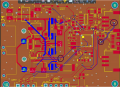
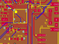
Hey all, this is my first PCB and I'd really appreciate some experienced eyes on it. It takes 18V in, generates 5V and 3.3V rails, and drives 4 series LEDs at constant current with PWM dimming, all controlled over a CAN bus. It's a 4-layer board (Signal / GND / 3V3 / Signal) built around an STM32F103C8T6 18V goes into an LMR51420 buck for 5V, which feeds a KTD2505R constant-current boost LED driver running 4 LEDs at 333mA, and an LM1117 LDO derives 3.3V for the MCU and a TCAN334 CAN transceiver with SWD and UART headers for programming and debug (I also added a USB just in case). I would appreciate any feedbacks. what are the 100% must-fix changes you'd make and what are some improvements that aren't critical now but you think I should know for next designs?
Thanks
Thanks
Attachments
-
 98.4 KB Views: 10
 -
412.4 KB Views: 14