PCB Design PIC18f4550

NorthGuy

Joined Jun 28, 2014
611
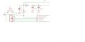
You should connect pin 1 of ICSP directly to the MCLR pin. You should also put a resistor between the MCLR pin and the point where C5 and R1 meet. 1K or even 470 Ohm should be ok.
 

Thread Starter

74266

Joined Mar 20, 2016
41
74 Is that 1 uF on the MCLR ? (C5) you can have .1uF but need to have a strap to disconnect it from the pin when programming ,
So what should I do in C5 ? change the value in 0.1uF?
hi 7,
Where are the connections to pin 15 and 16 . the power rails.?

E

EDIT:
Also check your 9 way D connections at the PIC end of the cable.
TX & RX ???
please check again my connection and I just added right now the pin 15 and 16
I am sure the 18F4550 has weak pullup resistors in PORTB that you need to enable prior using. Maybe it could help. Ah, you enable all or none.
so what do I need to change in port B
 

Attachments

atferrari

Joined Jan 6, 2004
4,769
so what do I need to change in port B
First read and understand what a pull up resistor is (precisely like the one you have applied to the pin 37).

Then read in the datasheet about PORTB to identify the register with a bit to enable the internal pullups that port B was designed with.

You need one resistor less and simplify your layout.

I use them all the time for a keyboard.
 

Thread Starter

74266

Joined Mar 20, 2016
41
Should work.
Thank You north guy but I want to clarify again, so it doesn't have any wrong connection and component's value now?

I also don't need to connect a resistor in every pin of RA-RD right?

And as you can see I also added a 8 LED separated to the main dev board in which the negative side of LEDS is connected in a pin that can be connected in VSS using connecting wire and I will just connect the PINS on the LEDS using connecting wire when I want to use them as OUTPUT
 
Top