PCB Design PIC18f4550

Thread Starter

74266

Joined Mar 20, 2016
41
Hello,
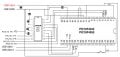
I plan to make a PCB design by basing it in this picture but my classmate said that there should be a capacitor connected in each leg of oscillator and there should be a resistor in pin 2 that is connected in vss and since port B will be mostly used I should put each resistor in each pin of port b
 

Attachments

ericgibbs

Joined Jan 29, 2010
18,849
hi,
It is usual to have low value cap to 0v on either leg of the xtal, a 12pF thru 22pF is common.
The other notes about resistors would depend upon the programs use of those pins.
Note there are 'weak' internal pull up resistors on PORTB in the PIC, which can be enabled.

If you are using the USB feature there should be cap on pin #18, Vusb to 0v, approx 0.47uF is common.

I would advise that you fit 100nF caps across pins #11 and 12 and also pins #31 and 32.

E
 
Last edited:

NorthGuy

Joined Jun 28, 2014
611
Your friend is right about capacitors. Have you ever looked at the datasheet? It has recommendations on the values of the capacitors depending on the crystal you use.

Pins 31 and 32 must be connected.

Your sketch shows resistors and capacitors, but doesn't show values. Wrong values can screw up everything.

RA0 and port B - depends on what you do.
 

Thread Starter

74266

Joined Mar 20, 2016
41
Your friend is right about capacitors. Have you ever looked at the datasheet? It has recommendations on the values of the capacitors depending on the crystal you use.

Pins 31 and 32 must be connected.

Your sketch shows resistors and capacitors, but doesn't show values. Wrong values can screw up everything.

RA0 and port B - depends on what you do.
what should I do in RA0? I plan to use 100 ohms for each pin in PORT B, for the other resistors I want to ask for suggestion for their value cause this already my 3rd time to develop a board
I will add a voltage regulator with capacitors,
mini usb type - B,
dc jack,
and pin header for every pins in pic18
also below is where I want to base it the components for the previous picture is also listed in there
 

Attachments

Last edited:

Thread Starter

74266

Joined Mar 20, 2016
41
Your friend is right about capacitors. Have you ever looked at the datasheet? It has recommendations on the values of the capacitors depending on the crystal you use.

Pins 31 and 32 must be connected.

Your sketch shows resistors and capacitors, but doesn't show values. Wrong values can screw up everything.

RA0 and port B - depends on what you do.
Also can I ask for a schematic for a pic18f4550 with max232 with dc jack, mini type usb and db9 if you have some
 

Attachments

NorthGuy

Joined Jun 28, 2014
611
If you connect PIC to MAX232, then simply connect direct. You don't need protective resistors inside your PCB. Just make sure they both run at the same voltage. This paper you linked has the schematics for MAX232, but it's sort of blurry and hard to read. You can look at MAX232 datasheet and they will have all the schematics. Datasheet is your friend. It has all the information, usually much more than you need.

What is the purpose of the converter - talking to old modems?
 

Thread Starter

74266

Joined Mar 20, 2016
41
If you connect PIC to MAX232, then simply connect direct. You don't need protective resistors inside your PCB. Just make sure they both run at the same voltage. This paper you linked has the schematics for MAX232, but it's sort of blurry and hard to read. You can look at MAX232 datasheet and they will have all the schematics. Datasheet is your friend. It has all the information, usually much more than you need.

What is the purpose of the converter - talking to old modems?
for the pin 2 of the max 232 should the positive part of the capacitor be connected in pin 2 at its negative part be in ground?

also please check please these schematic I cant find out why it is not compatible to mplab
 

Attachments

NorthGuy

Joined Jun 28, 2014
611
MAX232: The capacitor on V+ has positive end connected to the pin. The capacitor on V- has negative end connected to the pin. Both go to the ground. It's all explained in the datasheet. Have you looked at it yet?

Why do you think it's incompatible with MPLAB?
 

Thread Starter

74266

Joined Mar 20, 2016
41
MAX232: The capacitor on V+ has positive end connected to the pin. The capacitor on V- has negative end connected to the pin. Both go to the ground. It's all explained in the datasheet. Have you looked at it yet?

Why do you think it's incompatible with MPLAB?
yes I have seen it but there are some schematic I saw in net that pin 2 is connected in vcc


MPLab: in the dev board I made it is getting an error in every program I made
 

Thread Starter

74266

Joined Mar 20, 2016
41
I just made a new dev board using my design but it has a problem again this time .My dev board was being detected by The PICKIT2 app but when I import the hex(In this hex it must only set the all the pins of RB) to test it but it was not showing an output. I just wanna ask for hel if you can solve this problem.
 

Attachments

atferrari

Joined Jan 6, 2004
4,769
I am sure the 18F4550 has weak pullup resistors in PORTB that you need to enable prior using. Maybe it could help. Ah, you enable all or none.
 

ericgibbs

Joined Jan 29, 2010
18,849
hi 7,
Where are the connections to pin 15 and 16 . the power rails.?

E

EDIT:
Also check your 9 way D connections at the PIC end of the cable.
TX & RX ???
 

Attachments

Last edited:

TQFP44

Joined Sep 3, 2016
51
74 Is that 1 uF on the MCLR ? (C5) you can have .1uF but need to have a strap to disconnect it from the pin when programming ,
 
Top