PB137 Problems

Thread Starter

MikeML

Joined Oct 2, 2009
5,444
I am using a PB137 battery-charger chip as a float-charger for a 12V 4.5AH Sealed Lead Acid Battery. I started by using the circuit shown on page 5 (Section 3 Application) of the PB137 Data Sheet., where it holds the float voltage at 13.70V. That works as advertised.

I have encountered a problem which runs contrary to the advertised feature that "Reverse leakage current less than 10uA" as shown on page 1 of the DS and Irev Reverse Leakage Current shown in Table 4.

For testing, I have used a current-limited regulated DC bench supply set to about 18V for the input source. I added the bypass caps as shown in the applications schematic. I connected the output to the SLA, and the charging current tapers nicely toward zero as the battery accumulates charge, settling out to near 13.70V.

However, the problem shows up if the input supply is disconnected (or set to zero volts). The DS implies that this is ok; that the current that flows backwards from the battery into the output terminal of the PB137 should be less than 10uA.

What actually happens is that the initial reverse leakage current is about 50mA, which then rapidly increases to over 0.4A as the PB137 goes into thermal runaway and meltdown. The energy to blow up the PB137 comes from the battery.

This is not a fluke; I have blown up three PB137s in an attempt to understand on what is going on. They all got seriously hot, melted and now show a short between all three leads. These were all from the same batch of ten ST branded parts that I bought from Digikey. So my question for the forum: has anybody else experienced this?

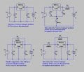
I have a workaround but it is not too elegant. I added a Si rectifier (1N4002) in series with the output lead (cathode toward the battery), which drops the output voltage by about 0.7V, but prevents any reverse current from flowing from the battery into the regulator output.

To compensate for the low output voltage, I added a small-signal Si diode (1N914) in the PB137 ground lead, cathode to ground. The regulator quiescent current (4 to 8mA) forward biases the diode, and raises the regulator output voltage by about 0.6V, which results in a final battery float voltage of ~13.5V, which I like better than the 13.7V from the intrinsic PB137, which is a bit too high for forever floating SLAs in my experience...

Any other suggestions?
 

THE_RB

Joined Feb 11, 2008
5,438
Try a diode from the output back to the input.

Then when Vin is disconnected and battery is at 13.7v (Vout pin), the Vin pin will be held at 13.7v - 0.6v = 13.1v which should be enough to still power it's internal current generator and protection circuit etc and stop it "freaking out".
 

Thread Starter

MikeML

Joined Oct 2, 2009
5,444
Thanks for the suggestions: Here are the results:


Question is: why would ST put out such a poorly specified product? Even if the input pin is "floating", I have seen the device go into the reverse-current induced thermal runaway. If the input pin comes from a wall-wart or other power supply that goes to zero volts (because the ACpower fails, for example), the reverse-current destruction of the PB137 is inevitable...
 

Attachments

Thread Starter

MikeML

Joined Oct 2, 2009
5,444
...
The bolded and italicized info is the "gotcha". This means you'll need to feed the PB137A via a diode. I'd suggest something like a 3.0A 1N5404; since the PB137 is rated for up to 1.5A, where a 1N4004 is only rated 1.0A continuous.
...

Since I have seen the PB137 go into reverse-current thermal runaway with the Input "floating", I am nervous about the diode-on-the input solution. I am going to go with the diode on the output and another in the ground lead.

Sure LA batteries should be equalized periodically, and the charger should be temperature compensated, however my application is room temperature, and I want to KISS.
 

SgtWookie

Joined Jul 17, 2007
22,230
I deleted my post after I'd re-read the thread and realized that you DID have the input floating. At this point, I suggest that you contact ST Microelectronics and tell them what you have found, along with (a) photo(s) of the faces of the ICs. It may be that Digikey's supply of PB137a's are counterfeit - even though Digikey is a reputable supplier, it still may be possible for them to get fakes.
 

THE_RB

Joined Feb 11, 2008
5,438
Since I have seen the PB137 go into reverse-current thermal runaway with the Input "floating", I am nervous about the diode-on-the input solution. ...
...
How does that even work? Isn't it the same effective circuit if the input is disconnected, whether the input diode is there or not? The input diode only has an effect is the input is shorted.

Maybe try putting a resistor from Vin to Vout, instead of the diode I suggested earlier. That will keep the two pins at the same voltage. If the battery is large (4.5Ah?) a resistor in parallel with the regulator should not affect regulation too much and that battery can easily absorb 50mA trickle without raising its final voltage so the resistor can be as low as a couple of hundred ohms.
 

Thread Starter

MikeML

Joined Oct 2, 2009
5,444
I repeated the tests, and here is a summary.


Case 1 is what is implied by the Data Sheet. If the Input is "open circuited" with the PB137 at room temperature, then only a miniscule current flows from the battery into Out, and the PB137 stays cool. The open-circuit voltage at In is about 0.6V lower than V(bat).

Case 2 leads to the destruction of the PB137. The only difference from Case 1 is that In was open-circuited with the PB137 heated by causing it to pass about 0.7A into the battery just prior to open-circuiting the input. At the instant the input was open-circuited, the reverse current from the battery backwards into the PB137 jumps to -0.5A which rapidly heats the PB137 to the melting point!

Case 3 is the configuration where I first noticed the problem. V2 and R2 represent a power supply that has a built-in bleeder resistor so that V(in) drops to near zero the instant the supply is turned off. This instantly causes the reverse current from the battery backwards into the PB137 to jump to -0.5A, which rapidly heats the PB137 to the melting point! It does not have to be hot to begin with...

Case 4 is a workable circuit. Per Mr RB's suggestion, R1 pulls V(in) up to near V(bat). The reverse leakage of the 1N5822 is tiny compared to what R1 can source. I tried this with the PB137 at about 120deg C and the reverse current is only a few uA. The "unregulated" charging current due to current flow into the battery through R1 is tiny compared to the intrinsic leakage of the battery itself...
 

Attachments

THE_RB

Joined Feb 11, 2008
5,438
Wow. Interesting. So it only complies with the datasheet and remains safe IF it's not hot? :eek:

Makes me wonder if you got a faulty batch, or crappy Chinese clones or something. Surely the design engineers would have checked that? It seems obvious the chip would need to protect itself from a loss of power at the input pin, as users do tend to unplug things from time to time! ;)

Glad you got a solution, and thanks for the heads up! I'll avoid that chip for sure.
 

RodneyB

Joined Apr 28, 2012
697
In
I repeated the tests, and here is a summary.


Case 1 is what is implied by the Data Sheet. If the Input is "open circuited" with the PB137 at room temperature, then only a miniscule current flows from the battery into Out, and the PB137 stays cool. The open-circuit voltage at In is about 0.6V lower than V(bat).

Case 2 leads to the destruction of the PB137. The only difference from Case 1 is that In was open-circuited with the PB137 heated by causing it to pass about 0.7A into the battery just prior to open-circuiting the input. At the instant the input was open-circuited, the reverse current from the battery backwards into the PB137 jumps to -0.5A which rapidly heats the PB137 to the melting point!

Case 3 is the configuration where I first noticed the problem. V2 and R2 represent a power supply that has a built-in bleeder resistor so that V(in) drops to near zero the instant the supply is turned off. This instantly causes the reverse current from the battery backwards into the PB137 to jump to -0.5A, which rapidly heats the PB137 to the melting point! It does not have to be hot to begin with...

Case 4 is a workable circuit. Per Mr RB's suggestion, R1 pulls V(in) up to near V(bat). The reverse leakage of the 1N5822 is tiny compared to what R1 can source. I tried this with the PB137 at about 120deg C and the reverse current is only a few uA. The "unregulated" charging current due to current flow into the battery through R1 is tiny compared to the intrinsic leakage of the battery itself...
In Cases 3 and 4 what is the value of R2 and R3
 

Thread Starter

MikeML

Joined Oct 2, 2009
5,444
R2 and R3 are just high-impedance bleeder resistors that would discharge the filter capacitor in the power supply, or the C2/C6 bypass capacitor... Even the leakage in a capacitor would eventually discharge the capacitor across the output of an AC supply if the AC supply is turned off.
 
Top