Part identification of a SMD and a UK sourced alternative.

Thread Starter

Masteryoda62

Joined Mar 12, 2020
10
Hi all.
Adrian here.
I'm hoping someone with technical knowledge can help me with the identification of a SMD and a UK sourced alternative.
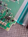
The SMD is from a car central display pcb and It seems to be getting a bit hot. The symptoms of the car are centre LCD display fading away. The backlight bulbs are all new and the display seems to work better from cold. As I have no wiring diagram it is a tad stab in the dark, but have attached a image. The dual sided PCB seems to have no obvious faults or damage, tracking the defective part is looking for excessive heat and hardest working components at present.

The SMD markings

UN or possibly UK in a circle.
R49
AH

If any one can ID and recommend a alternative would be helpful.

The SMD package measures 6mm width.
Legs measure 1mm from each of the edges and 3mm central. On the other side is 1 x larger leg which is central and 3mm wide.

Help appreciated. TY.
 

Attachments

jpanhalt

Joined Jan 18, 2008
11,087
Last edited:

Irving

Joined Jan 30, 2016
4,996
Thats almost certainly a voltage regulator. A possible part is a ML62492P which is a 4.9v LDO regulator. If its getting hot its unlikely that is the cause, that's the result. It has thermal shutdown so is probably being asked for too much current (it's spec'd as 170mA output).

1594983811955.png

measure input volts from tab to ground pin 1, measure output volts from pin 3 to ground pin 1, should be 4.9v but if the issue is overload you should see this drop as lights dim per your description. You then need to track down failing device elsewhere... likely to be a capacitor but could be other things...

Edit: Changed to better fit part and added datasheet
 

Attachments

Last edited:

Thread Starter

Masteryoda62

Joined Mar 12, 2020
10
Thats almost certainly a voltage regulator. A possible part is a ML62492P which is a 4.9v LDO regulator. If its getting hot its unlikely that is the cause, that's the result. It has thermal shutdown so is probably being asked for too much current (it's spec'd as 170mA output).

View attachment 212344

measure input volts from tab to ground pin 1, measure output volts from pin 3 to ground pin 1, should be 4.9v but if the issue is overload you should see this drop as lights dim per your description. You then need to track down failing device elsewhere... likely to be a capacitor but could be other things...

Edit: Changed to better fit part and added datasheet
Thankyou all for your replies so far and links. I will take a look when I get home later or over the weekend. I think you are correct re not being the root cause as this a few hours ago the display had gone completely dark so lost its backlights again. I could see the display and information was still working by shining a light through the back of the lcd display. So it is functional, just a backlight drive issue.

There were 2 x 22mfd smd caps nearby so I removed them and hug some normal 22mfd electoytic caps on the board to rule them out. It has ruled them out as it still does the same thing. It has also shown measuring across theses capacitor in fault condition I am missing a 12V supply. This 12V seems to be present when the display is on and working fine. So I will try to trace down where I am losing supply and whether this IC is part of that circuit. Thanks for the links and possible manufacturer and go from there. I will need a few days as a bit busy, but I will let you know how I get on.

Kind regards
Adrian
 

Thread Starter

Masteryoda62

Joined Mar 12, 2020
10
I suspect the manufacturer is ON Semiconductor:
View attachment 212343

Could be a linear voltage regulator. That is not a typical part number, but it may be another code. If you sort by package type, there are not that many to consider: https://www.onsemi.com/products/pow...tors/ldo-regulators-linear-voltage-regulators

EDIT: Dimensions are close for an SOT-223 package: https://www.mouser.com/datasheet/2/308/NCP1117-D-1595886.pdf
Thanks. Will look over the weekend.
 

Thread Starter

Masteryoda62

Joined Mar 12, 2020
10
Thats almost certainly a voltage regulator. A possible part is a ML62492P which is a 4.9v LDO regulator. If its getting hot its unlikely that is the cause, that's the result. It has thermal shutdown so is probably being asked for too much current (it's spec'd as 170mA output).

View attachment 212344

measure input volts from tab to ground pin 1, measure output volts from pin 3 to ground pin 1, should be 4.9v but if the issue is overload you should see this drop as lights dim per your description. You then need to track down failing device elsewhere... likely to be a capacitor but could be other things...

Edit: Changed to better fit part and added datasheet
Will do future work. Thanks for the help.
 

jpanhalt

Joined Jan 18, 2008
11,087
Thankyou all for your replies so far and links. I will take a look when I get home later or over the weekend. I think you are correct re not being the root cause as this a few hours ago the display had gone completely dark so lost its backlights again. I could see the display and information was still working by shining a light through the back of the lcd display. So it is functional, just a backlight drive issue.

There were 2 x 22mfd smd caps nearby so I removed them and hug some normal 22mfd electoytic caps on the board to rule them out. It has ruled them out as it still does the same thing. It has also shown measuring across theses capacitor in fault condition I am missing a 12V supply. This 12V seems to be present when the display is on and working fine. So I will try to trace down where I am losing supply and whether this IC is part of that circuit. Thanks for the links and possible manufacturer and go from there. I will need a few days as a bit busy, but I will let you know how I get on.

Kind regards
Adrian
If it is just the display, is it character or graphical? Does the device allow you to dim the backlight or turn it off?

The backlight is possibly just LED's. There may be a transistor (mosfet or BJT) to drive them. There is a resistor to limit current. That is where I would look. The LED's themselves probably do not fail, but can. The pinout on various displays is pretty common. If you have pictures of its connections or identification of the display, we may be able to locate the driver pin for a voltage test.
 

Thread Starter

Masteryoda62

Joined Mar 12, 2020
10
If it is just the display, is it character or graphical? Does the device allow you to dim the backlight or turn it off?

The backlight is possibly just LED's. There may be a transistor (mosfet or BJT) to drive them. There is a resistor to limit current. That is where I would look. The LED's themselves probably do not fail, but can. The pinout on various displays is pretty common. If you have pictures of its connections or identification of the display, we may be able to locate the driver pin for a voltage test.
It is a character only LCD with 3 x 12v 2Watt back light bulbs similar to those found behind a cars instrument panel. The lights can be adjusted by pushing a button on the speedo display panel and this has been set to its brightest setting. So the speedo display is okay. Just the central information panel displaying time, date and radio information. There may be a addition of a daylight sensor being part of the circuitry. I have tried to cover what I believe to be the daylight sensor in case this is playing about, but I get no difference. There was a few 22mfd smd capacitors to the left of the probably rectifier. Also between the reg IC and caps are the 4 pin outs that feed the display bulb board. To the left of the Reg IC on the image. When the display faded last time I measured across the electoytic cap and seem to be losing supply voltage. It seems worse in daylight, but I think that is heat related as the sun shines directly on top of it. As the weather cools down the display increases its visibility, but typically the car has either been off for a while or the sun is not as bright or hot. So it could be a problem with the display driver if fitted, but it only effects this centre console. My current plan when I can get to the car because works has to be done in situ, is try to find out what is happening to the supply voltage and where it is coming from.
 
Last edited:

Irving

Joined Jan 30, 2016
4,996
Yes, i wondered about that size difference, but none of the data sheets for a 4.9v part I looked at list a SOT-223-4 variant. It could therefore be a 5v part but the code makes no sense then. Mind you, SMD codes often don't make any sense.

@Masteryoda62 It gets more complicated however... and you need to do some measurements on all 4 pins relative to ground to confirm if pin 3 is an input or an output...

Here's my thinking...

VR offered in the SOT-223 case come in various pinouts, with pin 3 being either Vin or Vout. Normally the bulk capacitance on a VR is on the output, which looking at the layout suggests to me that pin 3 is output (The admittedly more common 1117 type being on pin 2) @SamR and @jpanhalt, do you agree or disagree?

(If they are the bulk output caps it wouldn't surprise me if one of those wasn't the culprit.)

If, as @SamR and @jpanhalt believe, it is an ONSemi part (I'm not convinced however) then its either an MC33275, an MC33375 or an NCV2931 as these are, according to the ONSemi parts selector, the only ones offered in the SOT223 package with Vout on pin 3. But these have different pinouts... (2931 same as 33275)

1594988389115.png1594988433674.png

Looking at the board layout closely it looks like pin 1 is connected to the via and also goes under the 10k resistor to what looks like an unpopulated pair of pads connecting back to Vout. If pin 1 is Vin then are the pads intended for another component from Vout to Vin eg reverse bypass diode?. Does it go to the 1k as well? Its hard to tell but the top end of the 10k appears to go nowhere else. If it does the 10k is input to output???

Pin2 goes nowhere obvious, but if its a control its has to be connected to Vin for on, grounding it turns the regulator off, which means you can't use a 33375 instead of a 33275.

So MC33275 or NCV2931 (automotive) have to be prime candidates...

On the other hand, if pin 3 is the input, pin 1 should be grounded. unless its used as an adjustable, in which case its connected back to the output via a resistor and to ground via another resistor elsewhere, possibly with slow-start added functionality. The layout might well support that ...

in which case an LM1117 (or NCV1117, its automotive equivalent) could be the one...

As an added thought, if that pic is representative of the state of solder joints on the board I'm not surprised there's a problem.. they could do with reflowing!


1594986992945.png
 

jpanhalt

Joined Jan 18, 2008
11,087
It is a character only LCD with 3 x 12v 2Watt back light bulbs similar to those found behind a cars instrument panel. The lights can be adjusted by pushing a button on the speedo display panel and this has been set to its brightest setting. So the speedo display is okay. Just the central information panel displaying time, date and radio information. There may be a addition of a daylight sensor being part of the circuitry. I have tried to cover what I believe to be the daylight sensor in case this is playing about, but I get no difference. There was a few 22mfd smd capacitors to the left of the probably rectified. Also a between the two are the pin outs that feed the display bulb board. I seem to be losing supply voltage when the display just fades away. It seems worse in daylight, but I think that is heat related as the sun shines directly on top of it. As the weather cools down the display increases its visibility, but typically the car has either been off for a while or the sun is not as bright or hot. My current play when I can get to the car because works has to be done in situations, is try to find out what is happening to the supply voltage.
Years ago, I had Buick with a speedometer display what was temperature sensitive. Of course,"no user serviceable parts inside." Opened it up and found a bad solder joint on a resistor/diode (don't remember which). Re-soldered and everything worked. I would trace back the power to those bulbs. In the days before PWM became commonplace large transistor were used for dimming. Today, it is more likely smaller mosfets or transistors. The temperature effect would make me suspicious of something simple like solder joints.
 

Thread Starter

Masteryoda62

Joined Mar 12, 2020
10
Yes, i wondered about that size difference, but none of the data sheets for a 4.9v part I looked at list a SOT-223-4 variant. It could therefore be a 5v part but the code makes no sense then. Mind you, SMD codes often don't make any sense.

@Masteryoda62 It gets more complicated however... and you need to do some measurements on all 4 pins relative to ground to confirm if pin 3 is an input or an output...

Here's my thinking...

VR offered in the SOT-223 case come in various pinouts, with pin 3 being either Vin or Vout. Normally the bulk capacitance on a VR is on the output, which looking at the layout suggests to me that pin 3 is output (The admittedly more common 1117 type being on pin 2) @SamR and @jpanhalt, do you agree or disagree?

(If they are the bulk output caps it wouldn't surprise me if one of those wasn't the culprit.)

If, as @SamR and @jpanhalt believe, it is an ONSemi part (I'm not convinced however) then its either an MC33275, an MC33375 or an NCV2931 as these are, according to the ONSemi parts selector, the only ones offered in the SOT223 package with Vout on pin 3. But these have different pinouts... (2931 same as 33275)

View attachment 212347View attachment 212348

Looking at the board layout closely it looks like pin 1 is connected to the via and also goes under the 10k resistor to what looks like an unpopulated pair of pads connecting back to Vout. If pin 1 is Vin then are the pads intended for another component from Vout to Vin eg reverse bypass diode?. Does it go to the 1k as well? Its hard to tell but the top end of the 10k appears to go nowhere else. If it does the 10k is input to output???

Pin2 goes nowhere obvious, but if its a control its has to be connected to Vin for on, grounding it turns the regulator off, which means you can't use a 33375 instead of a 33275.

So MC33275 or NCV2931 (automotive) have to be prime candidates...

On the other hand, if pin 3 is the input, pin 1 should be grounded. unless its used as an adjustable, in which case its connected back to the output via a resistor and to ground via another resistor elsewhere, possibly with slow-start added functionality. The layout might well support that ...

in which case an LM1117 (or NCV1117, its automotive equivalent) could be the one...

As an added thought, if that pic is representative of the state of solder joints on the board I'm not surprised there's a problem.. they could do with reflowing!


View attachment 212346
Okay. Understood. I'll try and fund out the pin outs, grounds and supplies. I am guilty of the soldering. Primarily because of lack of room and a large soldering iron bit, but that is repairable. The two capacitor nearby I have substituted with electroytic caps. Didn't improve anything. Work delayed as it is my wifes car and supply voltages been to be tested in the car hanging over the dash. I can do continuity tests easier in the house. Problem is I have to wait for car. It doesn't stop it running if I unplug it. I believe from car forums I could replace it and that will rectify the problem. There is no fun in that. Plus it would indicate the fault is on the board somewhere.
 

Thread Starter

Masteryoda62

Joined Mar 12, 2020
10
Years ago, I had Buick with a speedometer display what was temperature sensitive. Of course,"no user serviceable parts inside." Opened it up and found a bad solder joint on a resistor/diode (don't remember which). Re-soldered and everything worked. I would trace back the power to those bulbs. In the days before PWM became commonplace large transistor were used for dimming. Today, it is more likely smaller mosfets or transistors. The temperature effect would make me suspicious of something simple like solder joints.
I think your on the right track with regards poor connection somewhere. Double sided print is not particularly easy on my eyes these days. I've been out of electronics for 30 years, but it is funny. When I started my colleague and tutor had aging eyesight and used to ask me the values of the components he couldn't see. Now I can see what his problems were as I am now having the same issues with smaller components. Please bear with me while I try to pick my way around it.
 

Irving

Joined Jan 30, 2016
4,996
I think your on the right track with regards poor connection somewhere. Double sided print is not particularly easy on my eyes these days. I've been out of electronics for 30 years, but it is funny. When I started my colleague and tutor had aging eyesight and used to ask me the values of the components he couldn't see. Now I can see what his problems were as I am now having the same issues with smaller components. Please bear with me while I try to pick my way around it.
Likewise, despite (or maybe because of) new glasses. I have a very bright daylight white LED lamp and a (cheap £20) USB microscope plugged into a 24" monitor... it helps a lot!

15 or so years back the dash on my beloved mk1 AudiTT (then about 5y old) started having issues with the LED display, it was one of several common faults. So I built a car emulator to plug it into & power it up, with inputs from various simulators of speed sensor, etc. I fault found & fixed probably 40-odd dashes that way (Audi's answer was a new complete binnacle at ~£1000 inc fitting) and the vast majority were poor joints, with the occassional donor part lifted from scrapped cars or Mk4 Audi A3 or Golf which had a different but similar dash.
 

Thread Starter

Masteryoda62

Joined Mar 12, 2020
10
Okay. So a little update. The component was removed to trace where the connections were going as it is just not very clear. It would seem that the 2 x middle pins are connected in the device, but actually no nowhere on the board. Looks like they are just anchor points. It looks like the device is being used as a rectifying diode only. I get about .6V difference on leg 1 and 3V so a bit of a red herring. Situation has been made worse because I accidentally had a drop of solder fall onto the one end of the LCD ribbon cable. So I have called it a day. I had replaced the only 4 x caps on the board and also resoldered numerous joints. Even removing the push in connector which led directly to the bulb holder PCB and hard wired it.
I would like to thank everyone who helped me with the part ID and I wish you all the best.
Thanks.
 
Top