I’m not understanding then. What you suggested earlier is a battery only solution. But that is not my goal. My goal is a battery supplemented by parasitic power through the control lines. I know I can do a battery or an external power supply. What I am trying to figure out is how to design a current limiter of 2mA.
My solution charges the battery when the comm lines are high, exactly what you asked for. Basically, I am just pointing out that with the diode and the proper battery, the 1K resistor is your current limiter.
What you are suggesting is a multi-wire version of the Dallas one-wire comms interface. @BobTPH is correct, you don't need any additional current limiting if you choose carefully.
Here's a crude simulation of a one-wire interface using a 2.4v battery, 1kbps comms 16 bits each way every 200mS. The line voltage never drops below 3v, and the current into the battery is self limiting - as long as the idle period is long enough between transmissions to ensure the battery is kept charged. Removing one diode and making the battery a 1 cell LFP works even better...
In this simulation the master on the RHS sends a 1mS start bit followed, 2mS later by 16 data pulses. At the slave end (LHS), I1 represents a 3mA current draw starting 2mS after the start pulse and lasting 80mS, and a 16 bit data packet is returned 40mS after the start bit. The combined battery voltage and 2 diode drops (2.4 + 2 * 0.6 = 3.6v) limits the charging current during idle to slightly over 1.3mA.
Your version would have multiple wires, making it even easier to avoid loading any single wire too much - the second simulation below shows a 2-wire interface using just Tx and Rx data-lines. As you can see, there is more power to play with, and still no complex current limiting required.
My solution charges the battery when the comm lines are high, exactly what you asked for. Basically, I am just pointing out that with the diode and the proper battery, the 1K resistor is your current limiter.
I don’t see where I asked to recharging the battery, at least through the signal lines.
I was not looking to charge, but to supplement the power supply during the line transitions. The goal was parallel power supplies—5 through the signal lines and one from a battery. The battery would not be discharged during signal idle times. Indeed, I wasn’t even thinking of a rechargeable battery—at least not through the signal lines—because I didn’t want the space for the charger circuit.
I like you suggestion. Power the circuit via the battery. But regardless, if charging through the signal lines I’m still limited to 2mA per signal line. Which goes back to my original post asking about the current limiter.
What you are suggesting is a multi-wire version of the Dallas one-wire comms interface. @BobTPH is correct, you don't need any additional current limiting if you choose carefully.
Here's a crude simulation of a one-wire interface using a 2.4v battery, 1kbps comms 16 bits each way every 200mS. The line voltage never drops below 3v, and the current into the battery is self limiting - as long as the idle period is long enough between transmissions to ensure the battery is kept charged. Removing one diode and making the battery a 1 cell LFP works even better...
In this simulation the master on the RHS sends a 1mS start bit followed, 2mS later by 16 data pulses. At the slave end (LHS), I1 represents a 3mA current draw starting 2mS after the start pulse and lasting 80mS, and a 16 bit data packet is returned 40mS after the start bit. The combined battery voltage and 2 diode drops (2.4 + 2 * 0.6 = 3.6v) limits the charging current during idle to slightly over 1.3mA.
Your version would have multiple wires, making it even easier to avoid loading any single wire too much - the second simulation below shows a 2-wire interface using just Tx and Rx data-lines. As you can see, there is more power to play with, and still no complex current limiting required.
All batteries are self-limiting - as the cell voltage approaches the supply voltage the charge current drops to zero - as long as the charge voltage is properly controlled so that it stays at or below the open circuit battery voltage. Here the charge voltage is controlled by the PU resistor and diode drop; it's sufficient to control charge current because it's tiny compared to the C rating of the battery, and nothing more is needed. You're over thinking the problem.
At high charge rates it's a different story. Current control is needed to prevent the battery overheating, particularly when highly discharged, but once battery volts nearly near maximum for the specific chemistry then the charge current will naturally fall away as long as the supply is voltage constrained.
I’m not understanding then. What you suggested earlier is a battery only solution. But that is not my goal. My goal is a battery supplemented by parasitic power through the control lines. I know I can do a battery or an external power supply. What I am trying to figure out is how to design a current limiter of 2mA.
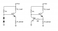
If that is all you need then why not try a current source type circuit. Since you do not need super accurate control, you can most likely get away with a transistor/2diodes/resistor solution.
A current source will put out any current below the set limit if the set limit is not reached, and if the set limit is reached then it will limit the current to the set limit.
Two circuits are shown in the attachment.
R1 will be relatively high in value. 10k maybe even more.
Rsense will have about 0.7v across it, so if Rsense was 0.7 Ohms (roughly) the current limit would be set at 1 amp. If Rsense is 7 Ohms, that means about 100ma, and 70 Ohms 10ma, etc., approximately (measurement required).
Rload is your intended load.
R2, if used, can be somewhat high too I think but a simulation is on order for either of these circuits.
This is a low side current limit, for a high side, use a PNP transistor and flip everything vertically.
In each design you find that coordinating pulse so that constructive interference occurs, also minimizing destructive interference related to harmonics can results in an improvement in electromagnetic transmission. The net effect is profound in very large generators however there are some clever small computer fans that use a hall effect sensor. Some charging designs use 1 wire and ground with power bank source uses an efficient step down converter and patented smart charge functions.
For the third time, it is the resistor that is limiting the current.
Do you understand how you use a resistor to limit the current to an LED? This is exactly the same. Instead of the LED Vf, use the diode Vf plus the battery voltage.
Again, I wasn't thinking of using the power from the control lines to charge the battery. Hence I wasn't seeing your particular solution. I was still thinking of the control lines in parallel with the battery and how to limit the current through those lines when they were sourcing current to the circuit (instead of the battery). All the connections were diode-or'd, so there was nothing propping up the voltage on the output of the diode-or.
But I now understand your point of putting the battery after the diode-or from all the control lines. So long as the voltage on the battery remains at least ~2.3V, then the drop across the resistor would be limited to about 2V, thus limiting the current to 2mA. But if the battery is low, then the current draw would be too large.
So it seems the problem remains. While it would be true that the system ought to operate fine, should the battery to go low or a device with a dead battery connected, it would drag the lines down until the battery voltage comes up. Now, this can be mitigated with some voltage detector to push the uC system into shutdown. That's a separate problem to consider/solve.
Yeah, but if you start with a battery, that should never happen, and the current is still limited to (5-0.6)/1000 = 4.4mA, so not disastrous. And things failing when a battery goes dead is something we are all used to.
For peace of mind, you could add a monitor circuit that lights an LED if the battery falls below 2.2V or so.
 Facebook
 Google
 GitHub
 Linkedin