P-ch MOSFET controlled by μC to drive a load

ericgibbs

Joined Jan 29, 2010
21,477
Please add the component files also in the zip file. They are issing
hi,
They are not missing, they are included in your original zip.

I have attached a zip which includes the MOS symbols.
Do you know how to place the files in the correct folders in your LTSpice folder?

E
 

eetech00

Joined Jun 8, 2013
4,709
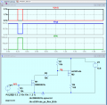
R2 is not needed in post#22 and will slightly slow down switching of the PMOS.
The software gpio output should be inverted to accommodate the addition of the NMOS transistor.

EDIT: R2 actually is needed because of +/-8v VGS rating.

1718564083753.png
 
Last edited:

Thread Starter

Jimis

Joined Jun 15, 2024
15
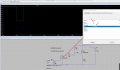
I don't know how to place the files in the SPICE folders. I used the external method No2 that says here.
http://denethor.wlu.ca/ltspice/add_model.shtml
Obviously something is not imported as it should.

The MODEL names inside those files say NMOS and PMOS respectively for each file which is actually ridiculous, I was expecting their Part Nos.
1718563892305.pngI
 

eetech00

Joined Jun 8, 2013
4,709
When Vg goes to 0 doesn't this mean that Vgs=-13.8V ? Isn't this too much for si2301cds to handle ?
And it looks like the models run fine in your project but not mine
Yes, I missed that on the PMOS datasheet. It has to be less than 8v. So R2 would be needed. But I would choose a PMOS mosfet with a higher VGS rating.
 

eetech00

Joined Jun 8, 2013
4,709
I don't know how to place the files in the SPICE folders. I used the external method No2 that says here.
http://denethor.wlu.ca/ltspice/add_model.shtml
Obviously something is not imported as it should.
Place the model files in the same folder as the schematic.
Then, remove the folder path from each .lib directive and just use the filename.

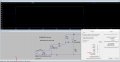
The MODEL names inside those files say NMOS and PMOS respectively for each file which is actually ridiculous, I was expecting their Part Nos.
View attachment 324807I
The names used for the mos transistors should match the names used in the spice model files.
Since the models are defined using ".subckt", the prefix in each mos symbol should be changed to "X" without quotes.
 

Thread Starter

Jimis

Joined Jun 15, 2024
15
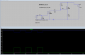
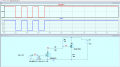
I'm having trouble running the simulation. Voltages look good but the simulation is not run completely. I should have 2 periods and the simulation seems to stop at 60%.

I read that these simulations with components like FETs can be tricky with small capacitances that need to be modeled but your screenshots show that your simulations worked fine so maybe smtg wrong with my setup.
 

Attachments

eetech00

Joined Jun 8, 2013
4,709
I'm having trouble running the simulation. Voltages look good but the simulation is not run completely. I should have 2 periods and the simulation seems to stop at 60%.

I read that these simulations with components like FETs can be tricky with small capacitances that need to be modeled but your screenshots show that your simulations worked fine so maybe smtg wrong with my setup.
M2 is upsidedown. The drain should connect to load.
 
Top