Over 0V Comparator With Unipolar Power Supply?

Thread Starter

johnyradio

Joined Oct 26, 2012
615
Application:
i'm making an over 0V detector, with a switchpoint of about 50 mV on the upward swing. Therefor, my ref would be connected to Ground. Desired output: Low = 0V, High = +V. Seeking lowest-parts count, so generally wondering which R's can be excluded.

Device:
Currently targeting the LM239 family, which according to datasheet is optimized for single supply.

Questions:
There are differences between TI and 3peak reference designs. Eg., 3peak has no ref R, but the TI design does.
  • What's the function of the ref R? What's drawback of not using it? Is it needed with the LM239 and a single-supply?
  • Same question re input R.
  • Same question re pullup R on the output.

3peak reference design:

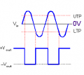
3peak-hysteresis

(In the 3peak reference design above, i'm guessing that the schematics showing the output connected directly to Vdd or ground is meant to indicate the state of the circuit when output goes high or low, respectively, and not that the output is physically connected to Vdd or ground with a wire. Correct?)

TI reference design:
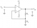
TI-hysteresis

(i assume Rload isn't an R in the design, it's the external load, correct?)

thx
 
Last edited:

Alec_t

Joined Sep 17, 2013
15,131
In the 3peak reference design above, i'm guessing that the schematics showing the output connected directly to Vdd or ground is meant to indicate the state of the circuit when output goes high or low, respectively, and not that the output is physically connected to Vdd or ground with a wire. Correct?
That's the only reasonable assumption. But the 3peak circuit won't work without a pull-up resistor on the output.
What's the function of the ref R? What's drawback of not using it? Is it needed with the LM239 and a single-supply?
It establishes a reference voltage above zero. Without it, whether or not the comparator works is at the mercy of the unknown input offset characteristic of the IC. Yes, it's needed.
 

Thread Starter

johnyradio

Joined Oct 26, 2012
615
Is it possible to wire a one-input OTS (off-the-shelf) Schmitt trigger, powered by a single-sided positive supply, such that it's triggered by a negative input voltage (below zero), without any additional parts?
1584400579477.png

Such as CD40106B or SN74LS14

Can it be done by reversing the power-supply pins (V+ and ground)?

If not, can it be done with a NAND Schmitt?

If not, can it be done with a resistor or two?

Or, with an analog inverter on the input?

Or, is a Schmitt built with an op amp or comparator and resistors the only way?
1584401132833.png

Seeking fewest-parts solution.
 

Attachments

Last edited:

crutschow

Joined Mar 14, 2008
38,573
Is it possible to wire a one-input OTS (off-the-shelf) Schmitt trigger, powered by a single-sided positive supply, such that it's triggered by a negative input voltage (below zero), without any additional parts?
How about three added resistors?
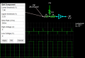
LTspice simulation below:

But that has both triggers on the negative part of the waveform.
If you want one trigger on the positive part, as you show in your waveform plot, then you will need to use the op amp or comparator circuit you posted, so you can have a greater hysteresis value.

1584422279711.png
 

Thread Starter

johnyradio

Joined Oct 26, 2012
615
Thx for that! But it seems the output doesn't cut out at the point expected.

1584428900265.png

My input spikes have a fast curve from about -4V (above the device threshold) to about -400 mV (well below the threshold).

@crutschow Does it make sense to you that this question was merged into a different topic?
 
Last edited:

Alec_t

Joined Sep 17, 2013
15,131
Is it possible to wire a one-input OTS (off-the-shelf) Schmitt trigger, powered by a single-sided positive supply, such that it's triggered by a negative input voltage (below zero), without any additional parts?
No. You need a resistor or two.
Here's a couple of minimal circuits.
The first uses a single Schmitt gate, with the usual hysteresis, and R2 can be tweaked to get the Schmitt to switch on a negative-going zero-crossing.
The second uses a pair of non-Schmitt gates with feedback to make a Schmitt with very little hysteresis, so that both positive-going and negative-going switching points can be close to zero.
NegativeTrigger.png
 

Thread Starter

johnyradio

Joined Oct 26, 2012
615
The first uses a single Schmitt gate, with the usual hysteresis.
The second uses a pair of non-Schmitt gates with feedback to make a Schmitt with very little hysteresis, so that both positive-going and negative-going switching points can be close to zero.
@Alec_t Brilliant way to solve two different questions (over-0 without hysteresis, under-0 with hysteresis). Awesome solutions!

@crutschow i think my negative-going spikes might not have been as high as i thought. Your circuit works well when input absolute-V is higher. Thx!
 
Last edited:
Top