Facebook
 Google
 GitHub
 Linkedin
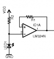 I'm trying to achieve an output that would influence a multiplexer input
 (74HC251). using the attached circuit, but I am unable to do so.
The LED1 is actually a photo-diode and the specs are located here:
http://futurlec.com/LED/INFD5940.shtml
My circuit has about 8 of them connected in parallel with anodes connected to each other and cathodes connected to each other.
What I used for R2 is 1 megaohm and for R1, I used 4.7 megaohm. Supply voltage comes from a 7805 voltage regulator with a 22uF decoupling capacitor. The source to the 7805 is a 9V battery.
I did some measurements with the voltmeter and with the battery at 6V, VCC of the opamp (also VCC to the resistor) is about 4V.
I then connected the meter between opamp pin 2 and ground and I applied a bright lazer beam onto the photodiode literally touching it, and the voltage changed by less than 0.5V.
I checked the output pin of the opamp as well and the results were still unsatisfactory.
The output I would ideally expect at pin 1 are two voltages depending on if light hits the photo-diode: sufficient voltage to produce a logic 1 to the input of the multiplexer (74HC251), or low voltage so logic 0 is produced.
I then proceeded to measure all the photodiodes together in parallel with the voltmeter using the ohms and then diode setting. With the ohms setting the meter didn't report anything, however when I set it to the diode setting and connected the meter anode to the diode cathode, and the diode anode to the meter cathode, I saw a 3-digit number on the meter that changed once a second for the first few seconds. When I reversed connection polarity, I got no reading.
Before assembling this whole thing on a breadboard like I did now, I used an unregulated VCC of 9V (instead of a max of 5V here) and I hooked an LED to the output with a resistor and when I passed the same light onto the photo-diode, the led changed from dim to bright, etc, responding to the light.
I begin to think my answer lies within changing part values to adapt to the 5V supply, but what values should I use?