 Facebook
 Google
 GitHub
 Linkedin
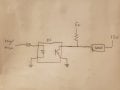
Hi all, Im working to design a circuit that can sink after a load is apply, but when there's no load also be able to output logic levels 5v/0v. The max that a load could be is 12V and not not more than 100ma, therefore I decided to use octocapulers to make some output logic. In my attach image, what I'm trying to accomplish is that when there is no load the output will be 5v or 0V. But when a load is connected be able to sink and drive the load. I know my image circuit won't work, but I just wanted to illustrate what I wanted to accomplish. Probably there are ICs or a good way to make a circuit to accept sourcing or sinking. Thank you.
Attachments
-
 2.7 MB Views: 30


