Facebook
 Google
 GitHub
 Linkedin
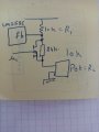
Hello, I want to design a variable voltage supply till 48 V@(0.1-1)A output with Input: 12 V/5V@(3A) input without a transformer. I have selected LM2586 but i am not sure of this IC still. As please can anyone suggest how can i proceed?
Thank you
Thank you