Oscilloscope Malfunction or Setting not properly done?

Thread Starter

Exjay

Joined Nov 19, 2015
186
Hello,

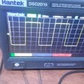
Please I bought an hantek 2d15 oscilloscope. I get the image in the attached when I used the add-on square wave output. Am I missing the setting or that's how the signal should be? I was expecting a very clean square wave with no harmonics at the low and high state.
 

Attachments

hexreader

Joined Apr 16, 2011
619
I do not own that oscilloscope, but ideas that come to mind are:

1 use DC coupling, not AC
2 make sure that Bandwidth Limit is turned off
3 use good quality 10:1 probes or 50 Ohm terminated coax
4 learn to expect less of a mid-price oscilloscope (not a dig at Hantek brand, just reality)

EDIT: - Your post motivated me to check out my Hantek 2D42 - different scope, but probably similar behaviour.
Internal AWG is noisy distorted and jittery. I would risk a small bet that yours is poor quality too.
Scope shows a fair quality (not good) square wave if I use a good quality external AWG.

I love my Hantek 2D42 for 90% of uses, but I expect little from it. A good quality bench scope is a must for more demanding diagnosis.
 
Last edited:

crutschow

Joined Mar 14, 2008
38,321
I see some noise but no harmonics.
Otherwise looks like a clean square-wave.

What does it look like when you turn the signal down to 0V?
 

Thread Starter

Exjay

Joined Nov 19, 2015
186
I do not own that oscilloscope, but ideas that come to mind are:

1 use DC coupling, not AC
2 make sure that Bandwidth Limit is turned off
3 use good quality 10:1 probes or 50 Ohm terminated coax
4 learn to expect less of a mid-price oscilloscope (not a dig at Hantek brand, just reality)

EDIT: - Your post motivated me to check out my Hantek 2D42 - different scope, but probably similar behaviour.
Internal AWG is noisy distorted and jittery. I would risk a small bet that yours is poor quality too.
Scope shows a fair quality (not good) square wave if I use a good quality external AWG.

I love my Hantek 2D42 for 90% of uses, but I expect little from it. A good quality bench scope is a must for more demanding diagnosis.
Thanks for your recommendation. How do I ensure bandwidth limit is not turned off?
 

Thread Starter

Exjay

Joined Nov 19, 2015
186
I want to measure the time constant of an RL circuit. I couldn't because of the noise generated along with the output.
 

Thread Starter

Exjay

Joined Nov 19, 2015
186
There is always noise present in any system. The amount of noise is relative.
Thanks for your response. I'm trying to solidify my basic electronics. Currently, I am learning RL circuit in response to square wave and sinusoidal function. I need to get the time constant from the waveform shown on the screen. So the wave generated is so imperfect that I can barely get meaningful thing from it.
 

hexreader

Joined Apr 16, 2011
619
How do I ensure bandwidth limit is not turned off?
You have it back to front - bandwidth limit should be OFF for squarest waveform display

Section 2.6.1 of the manual - paragraph 3
Second item in table - switch to off - do this for both channels
Note that noise may be higher with BW limit off, but square wave will be squarer.

Read manual section 1.6 carefully and perform probe set up for both probes

Since your main issue seems to be noise, you may want to hide some of the noise using using the bandwidth limit ON setting.
Better solution is to fix the cause of the noise:
- Circuit construction on solderless breadboard is likely to be noisy
- Increase input signal level such that the signal is larger, making noise a lower proportion of the signal (signal to noise ratio)
- Be sure to connect both probe ground leads to ground at the circuit end
- Try switching probes between X1 and X10 to see which gives least noise

Think about your RL circuit - If you are feeding in, for example, 5Vpp in, and getting only 1mVpp out, then of course such a low voltage will be difficult to measure. Try different values of R, L or frequency to give a decent signal out
 
Last edited:

MrChips

Joined Oct 2, 2009
34,628
How does noise affect your ability or inability to measure RC and RL time constant on an oscilloscope?
The period of the square wave ought to be in the order of magnitude of the RC or RL time constant.
In other words, your waveform should look something like this:

1724160116103.png
 

Thread Starter

Exjay

Joined Nov 19, 2015
186
You have it back to front - bandwidth limit should be OFF for squarest waveform display

Section 2.6.1 of the manual - paragraph 3
Second item in table - switch to off - do this for both channels
Note that noise may be higher with BW limit off, but square wave will be squarer.

Read manual section 1.6 carefully and perform probe set up for both probes

Since your main issue seems to be noise, you may want to hide some of the noise using using the bandwidth limit ON setting.
Better solution is to fix the cause of the noise:
- Circuit construction on solderless breadboard is likely to be noisy
- Increase input signal level such that the signal is larger, making noise a lower proportion of the signal (signal to noise ratio)
- Be sure to connect both probe ground leads to ground at the circuit end
- Try switching probes between X1 and X10 to see which gives least noise

Think about your RL circuit - If you are feeding in, for example, 5Vpp in, and getting only 1mVpp out, then of course such a low voltage will be difficult to measure. Try different values of R, L or frequency to give a decent signal out
Thanks for taking your time to direct me to the special portion of the manual. I will give a feedback
 

Thread Starter

Exjay

Joined Nov 19, 2015
186
How does noise affect your ability or inability to measure RC and RL time constant on an oscilloscope?
The period of the square wave ought to be in the order of magnitude of the RC or RL time constant.
In other words, your wave form should look something like this:

View attachment 329634
Wow! Such a neat waveform. I will send my picture in when I have applied the advice from here.
 

Thread Starter

Exjay

Joined Nov 19, 2015
186
I think I suck at working with inductors. When I connect two inductors, 33mH and 47mH, in series with 680 ohms resistor. I get the same square waveform as the input across the inductors. Is this normal?
 

Thread Starter

Exjay

Joined Nov 19, 2015
186
I think I suck at working with inductors. When I connect two inductors, 33mH and 47mH, in series with 680 ohms resistor. I get the same square waveform as the input across the inductors. Is this normal?
I used 300Hz square wave
 
Top