 Facebook
 Google
 GitHub
 Linkedin
So I made a basic transformer based probe to do some investigation on my TIG welder which doesnt work and has a "low input voltage" error.
It's not perfect but should help me do some basic testing, relatively safely. [I am aware of the risks and do decharge capacitors before going anywhere near them, i have probed mains equipment with multimeters for many years, now adding osciloscope to see wave forms]
I reveived some helpful advice on this probe in a previous post: https://forum.allaboutcircuits.com/threads/measuring-mains-in-an-oscilloscope.203885/
Now I see some strange readings/behaviour which I don't understand at all. My steps and observations are below;
(I live in England btw)
-measure mAins voltage with multimeter at 245v rms
- use transformer probe to measure same mains as : +/= 14v peak, 10v rms. Multimeter and scope give similar readings
-i therefore "calibrate" my probe; Vreal = ~24 * Vmeasured , all simple enough so far...
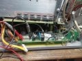
-now i move to the TIG welder. The board in the photo, i believe is a filter for the mains in, before the power goes to rectifier, inverters etc. There are two sets of wires coming out of the board, each reading ~120v with DMM. so i guess the welder splits the voltage to use lower power/cheaper components downstream..
-First question: i would expect the red, black and yellow to be"live" "neutral" and "earth", but measuring red and black with DMM gives me 0v. Red/yellow of Black/yellow gives 120v. confused why this is the case, seems more than just a different colour convention?
-And here's the funny part: When i add the transformer probe to red/yellow the measure voltage reads;
~25v RMS with DMM and ~1.2v RMS with scope (my calibration factor *24 =~25)
as soon as i disconnect the transformer probe, the DMM reading jumps to 120v! i dont get it at all....( i get the same result even if the transformer probe is not connected to the scope)
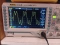
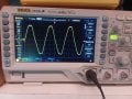
the waveform has some kinks from the capacitors, but otherwise looks reasonable.
any insight on this would be appreciated!
i already see the filter circuit is not the problem with the TIG just using the DMM, but ideally i can understand the behaviour of this probe for next steps of the troubleshooting.")
It's not perfect but should help me do some basic testing, relatively safely. [I am aware of the risks and do decharge capacitors before going anywhere near them, i have probed mains equipment with multimeters for many years, now adding osciloscope to see wave forms]
I reveived some helpful advice on this probe in a previous post: https://forum.allaboutcircuits.com/threads/measuring-mains-in-an-oscilloscope.203885/
Now I see some strange readings/behaviour which I don't understand at all. My steps and observations are below;
(I live in England btw)
-measure mAins voltage with multimeter at 245v rms
- use transformer probe to measure same mains as : +/= 14v peak, 10v rms. Multimeter and scope give similar readings
-i therefore "calibrate" my probe; Vreal = ~24 * Vmeasured , all simple enough so far...
-now i move to the TIG welder. The board in the photo, i believe is a filter for the mains in, before the power goes to rectifier, inverters etc. There are two sets of wires coming out of the board, each reading ~120v with DMM. so i guess the welder splits the voltage to use lower power/cheaper components downstream..
-First question: i would expect the red, black and yellow to be"live" "neutral" and "earth", but measuring red and black with DMM gives me 0v. Red/yellow of Black/yellow gives 120v. confused why this is the case, seems more than just a different colour convention?
-And here's the funny part: When i add the transformer probe to red/yellow the measure voltage reads;
~25v RMS with DMM and ~1.2v RMS with scope (my calibration factor *24 =~25)
as soon as i disconnect the transformer probe, the DMM reading jumps to 120v! i dont get it at all....( i get the same result even if the transformer probe is not connected to the scope)
the waveform has some kinks from the capacitors, but otherwise looks reasonable.
any insight on this would be appreciated!
i already see the filter circuit is not the problem with the TIG just using the DMM, but ideally i can understand the behaviour of this probe for next steps of the troubleshooting.
Attachments
-
 821.2 KB Views: 13
 -
 622.8 KB Views: 15
 -
 588.9 KB Views: 14


