Measuring mains in an oscilloscope

Thread Starter

Gizer

Joined Aug 15, 2017
52
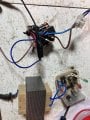
I need to test some mains voltage circuits in an acdc tig welder and i used a wall socket transformer in the past as a poor man’s differential prob

from the ratio of measured voltage and i scale up measurements.

i read that theae transformers are designed to operate close to saturation so wondered how i can check this:

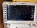
waveform seems/looks reasonable but how do you determine any clipping or if its distorted? (I dont know all the functions of my scope yet!)

also, if i use a more powerful transformer (rates for higher current), is this leas likely to become saturated?

i would use two transformers but i dont have two with similar voltages…

Finally, for general waveform inspections, transformers seem a reasonable way to probe mains voltages, what does the few hundred pounds/dollars get you extra for a differentila probe?
 

Attachments

drjohsmith

Joined Dec 13, 2021
1,548
Have you considered a voltage divider ?
Some big resistors ?
Why do you need differential probe ?
Do you have two probes / traces , can you display the difference between the two traces ?
 

Ian0

Joined Aug 7, 2020
13,097
Use a x100 probe. They are intended for high voltages and come will insulated with an insulated BNC plug.
First check the neutral-to-earth voltage, and hopefully you will find that it is almost zero.
Then you can measure live-to-earth with the x100 probe with the earth clip disconnected instead of live-to-neutral and you know that you will be getting the same measurement.
 

Thread Starter

Gizer

Joined Aug 15, 2017
52
Have you considered a voltage divider ?
Some big resistors ?
Why do you need differential probe ?
Do you have two probes / traces , can you display the difference between the two traces ?
I did consider a voltage divider but didnt have the parts whereas i have a few transformers lying about.

i thought diff probe was the proper tool for the job..

i do have 2 traces/probes and i know you can measure mains this way but i really dont want to blow up my scope accidently shorting the mains :)
 

Thread Starter

Gizer

Joined Aug 15, 2017
52
Use a x100 probe. They are intended for high voltages and come will insulated with an insulated BNC plug.
First check the neutral-to-earth voltage, and hopefully you will find that it is almost zero.
Then you can measure live-to-earth with the x100 probe with the earth clip disconnected instead of live-to-neutral and you know that you will be getting the same measurement.
ah of course, i had heard of 100x probes (voltage divider i guess?) but had forgotten and was looking at diff probes…

i see theyre pretty cheap so no brainer to get one… one question though, if a cheap one fails, will it fail dramatically or in the right way? ( surge, short mains destroy scope or divider stopa working and no measurements)

cheers

(also bit confused what a diff probe is for if you can simply use 2 traces + math functions, i thought high voltage was their main use!)
 

Ian0

Joined Aug 7, 2020
13,097
i see theyre pretty cheap so no brainer to get one… one question though, if a cheap one fails, will it fail dramatically or in the right way?
I've never know one fail. They contain a 100MΩ resistor, so it's a bit unlikely you could damage it, and are generally rated to over 1000V
 

drjohsmith

Joined Dec 13, 2021
1,548
ah of course, i had heard of 100x probes (voltage divider i guess?) but had forgotten and was looking at diff probes…

i see theyre pretty cheap so no brainer to get one… one question though, if a cheap one fails, will it fail dramatically or in the right way? ( surge, short mains destroy scope or divider stopa working and no measurements)

cheers

(also bit confused what a diff probe is for if you can simply use 2 traces + math functions, i thought high voltage was their main use!)
Can a cheap probe fail ?
You pay for what you get.
Failure is always an option , even in a transformer .
All I can say, is it's normal to measure many thousand of bolts using probes designed for the job.
Better ones have things like strings if resistors , and safety resistor types , not your off the shelf 0805. They are designed to fail open.
Differential probes .
Are not for high voltage . The scope is still referenced to ground , and differential proves have limits as to how far off ground the common voltage of the measured pair can be. Some probes it's a few volts .. measuring mains with them will if your lucky give bad readings , unlucky blow the probe, very unlucky blow the scope or you .
The maths function on the scope is there for just this sort of measurement .
 

drjohsmith

Joined Dec 13, 2021
1,548
When testing mains connected systems with a mains powered scope there is a serious need oof isolation required
Not true for the measurement. We work with 10kv lines , and use resistive probes designed for the job.
Now @MisterBill2 , if your saying working on a mains TV, then yes it's good practice to use an isolation transformer on the TV mains, but I'd still not earth my scope to the chassie of the TV.
 

Pyrex

Joined Feb 16, 2022
501
Hi,
A transformer is a good solution for the safety. On the other hand, for accurate reading you need to use a specifically made transformer , a wideband one.
As a cheap solution, you can use ar 400V rated transformer in 230V mains. It will not saturate, so readings are more accurate compared to a 230V rated transformer.

A good solution is to use Isolated Probe :

IsoVu Isolated Probes | Tektronix
 

MisterBill2

Joined Jan 23, 2018
27,159
OK, the isolation transformer should be used to isolate the scope from the mains, and the scope safety ground needs to be disconnected, when probing a non-isolated mains powered circuit. Otherwise there is the likely-hood of damaging the scope.

By properly isolating the scope the waveform distortion is removed.

CERTAINLY THERE IS A REQUIREMENT FOR CAUTION WHEN THIS IS DONE. No question about that.
Having the scope common connected to mains potentials requires a great deal of extra caution, including preventing unwitting individuals from participation.

The choice made in our organization was to use the small battery powered, well insulated,portable scope, when that choice would work.
 

drjohsmith

Joined Dec 13, 2021
1,548
OK, the isolation transformer should be used to isolate the scope from the mains, and the scope safety ground needs to be disconnected, when probing a non-isolated mains powered circuit. Otherwise there is the likely-hood of damaging the scope.

By properly isolating the scope the waveform distortion is removed.

CERTAINLY THERE IS A REQUIREMENT FOR CAUTION WHEN THIS IS DONE. No question about that.
Having the scope common connected to mains potentials requires a great deal of extra caution, including preventing unwitting individuals from participation.

The choice made in our organization was to use the small battery powered, well insulated,portable scope, when that choice would work.
I'd never advise to remove a safety earth on some test equipment. They are there for a reason , and there is no need to do so.
If I did that on one of our test sets , it's instant dismissal.
 

MisterBill2

Joined Jan 23, 2018
27,159
I'd never advise to remove a safety earth on some test equipment. They are there for a reason , and there is no need to do so.
If I did that on one of our test sets , it's instant dismissal.
YOU WILL NOTICE that I repeatedly mentioned the numerous safety cautions!!

Certainly safety rules are crafted to thwart "natural selection", and certainly the evidence points out that the intent is satisfied.
And I NEVER suggested REMOVING that safety earth connection, but rather providing adequate isolation from the earth connected scope system common.

For those folks unwilling or unable to safely work with mains voltages, it makes perfect sense to restrict their activities to the 5 volt and 3.3 volts systems.
Of course, I would not allow such individuals to enter any technical area either.
 

ronsimpson

Joined Oct 7, 2019
4,645
I'd never advise to remove a safety earth on some test equipment.
I have floated my old metal cased Tektronix scope decades ago. Very dangerous.

1) I have an isolated, handheld, battery powered, scope. I think it is rated to 4kV. All the buttons and case are double insulated. It has special probes where you cannot touch the scope ground. The two probes are not isolated from each other. I use it mostly for power line measurements and power supply tests.
1731463566256.png
2) When I need a real isolated scope. We have a different model of this. The 4 probes are isolated from each other. Up to 1kv. Must be a different model because I was using it above well 1K ChanA to ChanB.
1731421173920.png
 
Last edited:

Externet

Joined Nov 29, 2005
2,624
As a kid, tinkering and learning, connected a oscilloscope probe to a mains wall outlet. And showed perfectly well the waveform. Nothing blew up, no sparks. But thinking later; I did not do it again. No clue what settings were when it worked but did not want to risk the instrument again.:oops:
 

ronsimpson

Joined Oct 7, 2019
4,645
I built some isolated diff probes using "isolation amplifiers". There are several different types on the market. Most have 100khz to 200khz bandwidth. Most at good to 1kv to 4kv isolation. Input voltage range is usually form 100mV to 5V. Some only input 0 to 5V while some to -5 to +5V. I needed to have isolation and small capacitance across the isolation. I think a have a drawer full of each of 20 versions of these. I would use the -0.1 to +0.1V 200khz version for an isolated probe. isolated amplifiers Here is a link. There are also "linear opto isolators" that are OK but I did not like them.
1731424512157.png
 

Thread Starter

Gizer

Joined Aug 15, 2017
52
Thanks for all the replies, i spent some time to read them all carefully. For some months i read plenty of other threads on osciloscopes and mains and appreciate its not a yes/no question…

i dont often need to do this and perfect accuracy is also not really necessary; my uses are usually on 240v mains at 50hz,

reading all the safety issues, i therefore thought the simple transformer solution was safe and good enough. I will probably get a 100x probe and compare to a transformer readings. I need to debug and check waveforms from a tig welder at different settiings so i think waveform and approx readings are fine which i will cross check with a multimeter…

i may try to get a 400v transformer to improve things or two 240 transformers primary in series think also works? With similar secondary voltage in parallel or something like that :)
 

MisterBill2

Joined Jan 23, 2018
27,159
As a kid, tinkering and learning, connected a oscilloscope probe to a mains wall outlet. And showed perfectly well the waveform. Nothing blew up, no sparks. But thinking later; I did not do it again. No clue what settings were when it worked but did not want to risk the instrument again.:oops:
IF you were a kid when I was a kid, there were no 3-wire safety ground outlets, AND, the scope was probably not new, and so the probe "common" side, while connected to the scope "common", was not tied to an "earth ground" (to somehow magically guard your safety). And the scope probably had a two pin mains power plug.
I have one of those older scopes, a Knight Kit "High Frequency" scope that boasted a 5.5 megacycle bandwidth, "suitable for color TV servicing." was the claim. It still works adequately for audio work, and for tracing issues on IF strings on some receivers.
 
Top