Facebook
 Google
 GitHub
 Linkedin
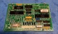
In the front left corner, note the unpopulated silkscreen for C68. That goes to pin 1 on the oscillator can next to it.
Do I assume correctly that it would have been for a trimmer cap? I don't believe I've ever come across a canned oscillator that had provision for an external trimmer.
Do I assume correctly that it would have been for a trimmer cap? I don't believe I've ever come across a canned oscillator that had provision for an external trimmer.
Attachments
-
 1.3 MB Views: 21


")