Facebook
 Google
 GitHub
 Linkedin
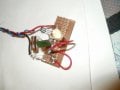
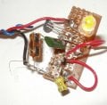
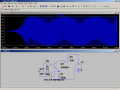
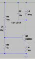
The attached oscillator works pretty well in SPICE, supply voltage is 19V and the transformer/inductor is wound on a small toroid. In the model I can change pretty much any component by a factor of 10 and it'll still oscillate. Design frequency is around 75 kHz
After building it and several days messing around I still can't get it to take off. I think the ferrite bead I used for my first attempt was just too lossy (looked like 10 ohms series R at 100 kHz but the inductances were right) but an air-core one and one with better ferrite didn't work either.
Tried so far:
Tweaking the turns ratio, inductances, core material.
Reducing the 10k for more bias
Shunting the 100R with a capacitor (more ac gain)
Shunting the 10k with a capacitor to give it more startup kick
Winding the supply up to 30V
Bypassing the input filter for more of a startup kick
Reversing the feedback winding in case I screwed up the phasing
Different transistors
Shouting at it
Any ideas please? It just doesn't have the look of a marginal design in the simulator so I suspect I've missed something obvious.
Attachments
-
 17.8 KB Views: 56
 -
2.8 KB Views: 27