Your unconventional style makes it difficult to read your schematics.
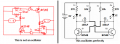
This is the classic discrete astable multivibrator circuit (from Wikipedia):
If the supply voltage is higher than the breakdown voltage of the base-emitter junctions, you need to install diodes antiparallel to those junctions to prevent the transistor from being damaged (kill beta).
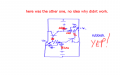
Heres the other one I did a few hours ago, no worky, no idea.
Yes I probably do Ian.
This one has 2 separate batteries running it, they both have a divider where the transistor opens up a short to discharge the cap, but nup didnt work.
Its another Astable multivibrator dual receptacle type design.
That astable multivibrator circuit, I should try and wire that together, see if that thing will work. I dove in to original design too early I think, I should just go take a few leaps back and just try some industry standard circuits and see if at least they work... (when its actually me happenning to plug the battery up to them... )
Not really. We don't draw transistors the way you've drawn them unless doing so conveys intent more clearly (as in a pass transistor for a power supply). Other than that, we draw them with the base lead horizontal.
Try to make it more like the schematic I posted from Wikipedia. You should also draw the arrow on the emitter so we don't get confused and assumed inverted mode operation instead of active/saturation.
We don't draw transistors the way you've drawn them unless doing so conveys intent more clearly (as in a pass transistor for a power supply). Other than that, we draw them with the base lead horizontal.
Instead of guessing, look at Transistor Multivibrator Circuits in Google and calculate the charging times of the capacitors to determine the frequency. Resistor values are simple to calculate:
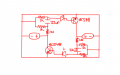
By looking at the collector and emitter connections of the transistors, you can see that it won't work. The first time either transistor is turned on, it will be destroyed because it will be shorting the power supply.
Something I neglected to mention about transistor orientation. Normal orientation for an NPN (or PNP) transistor is for the emitter to be below the collector. There are always exceptions, but your usage isn't one of them.
Obviously. But if you want others to be able, or want, to read your schematics, you should use standard conventions. If you want to be unconventional, don't ask more conventional engineers/technicians for help.
Obviously. But if you want others to be able, or want, to read your schematics, you should use standard conventions. If you want to be unconventional, don't ask more conventional engineers/technicians for help.
no I value everyones help here, much good advice and lots of knowhow about little odds and ends that can be a real pain to have to go about working out all by your lonesome, I just didnt know how tricky things were going to be on the internet about electronics. I thought it was just going to be like my little kiddie programming forums... but no... something was different...
I just didnt know how tricky things were going to be on the internet about electronics. I thought it was just going to be like my little kiddie programming forums... but no... something was different...
If everyone could do that, then everyone could be an electrical engineer/technician. I went to school for years to learn this stuff.
Of course, that was before the internet had been invented...
On the other hand, books still haven't been written for much of what I did at work for the last couple decades of my career. It's always going to be that way with the bleeding edge of technology. But my work was in the area of state-of-the-art process technologies, not electrical engineering...
I worked on a chip design (I was on the software side) that had a ring oscillator to clock a PLL which provided the CPU clock. It was supposed to have 5 inverters in series. But the “smart” design software optimized away one of the inverters, leaving 4. First silicon came out that way, DOA.
C1 is charged by R1, L1 and the 0.7V base-emitter diode of Q2 causing Q2 to be turned on then C2 turns off Q1.
When C2 is discharged by R3 then Q1 turns on by R3 then C1's negative pin is driven to a few negative volts which turns off Q2 then C1 is discharged by R2.
C2 is charged by R4, L2 and the 0.7V base-emitter diode of Q1 causing Q1 to be turned on then C1 turns off Q2.
When Q2 turns on by R2 then C2's negative pin is driven to a few negative volts which turns off Q1 then C2 is discharged by R3
then C2 is discharged by R3.
 Facebook
 Google
 GitHub
 Linkedin

 )
)