 Facebook
 Google
 GitHub
 Linkedin
Hello everyone. This is my first post here. I am an aircraft electrical systems instructor and the facility I teach at has a course for the NCATT certification that I am going to be teaching. I have the license, but the majority of my experience and knowledge is to the systems, not the internal circuitry of the components. The only part that I'm going to be teaching that I am struggling with is two of the four types of oscillators.
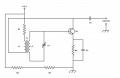
We talk about the Armstrong, Hartley, Colpitts, and crystal-controlled Pierce oscillators. The reference material I have from the old NCATT website (really, it's just older Air Force training documents) only goes into detail about the Hartley and Pierce. While trying to get more info I've realize that the diagrams I have for the Armstrong and Colpitts are not found anywhere on the internet that I have been able to access. I understand the concepts and for the most part what each component is doing, but my biggest issue is signal/current flow.
I'm attaching the images for the Armstrong and Colpitts oscillators. Could someone help to explain how the BJT is being biased and the current flow (by the way, NCATT teaches electron flow, negative to positive, so that would be preferred) as it pertains to initial power input, the feedback network, and output signals.
I really appreciate any help I can get.
Attachments
-
 66.6 KB Views: 22
 -
 73.9 KB Views: 20


