
Hi experts
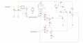
I was designing a programmable power supply 0-30v/0-4A.The control part is based totally on analog electronics.By far,my power supply is working as expected.But the main problem is the current control loop.Whenever the control loop is limiting current,I can hear humming sound from the Q1(In my schematic,it is TIP41 but in i am using MJE15032).I have captured the waveform of the Current control op-amp's output & the main output.Also the main output is fluctuating between 1V window.(For say,if i have set the output to 5v,then it is going to 6v).
The op-amp i am using is LT1013.The IC2(LM317) is powering the op-amps at 33v.The main power transistor(T1) is TIP35.Please take a look at the schematics.Is the oscillation normal?If not,then how to clear it??
Attachments
-
 268 KB Views: 13
 -
146.3 KB Views: 5
-
146.3 KB Views: 4


