Facebook
 Google
 GitHub
 Linkedin
Hi
I'm hoping some of you could help me with a design "problem" I'm having.
I'm making a laser harp/theremin for a school project, I'm using a Arduino but are doing most of the signal processing analog.
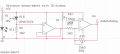
My laser beam detector design is a voltage divider with a photoresistor -> an active 1st order active low pass filter -> op-amp comparator
As far as I know this is an ok order?
Her in Norway I'm not allowed to own powerful enough lasers (without a permit) to use the reflected laser to measure distance. Since I want to control other aspects of the sound like volume or a filter I'm using a IR diode system to measure the distance of the hand from the sensor. I know I could use this to trigger the note also, but no laser harp without lasers") .
.
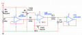
In this IR system I'm using a voltage follower -> a differential amplifier with two potmeters to get as close to 0-5V as I can for the Arduino.
I'm adding a low pass filter to this part as well and was wondering on the order or if I need the voltage follower at all (since my first order active low pass filter has a voltage follower).
If I still need it, would it be best to buffer the signal before the filter or after?
I'm hoping some of you could help me with a design "problem" I'm having.
I'm making a laser harp/theremin for a school project, I'm using a Arduino but are doing most of the signal processing analog.
My laser beam detector design is a voltage divider with a photoresistor -> an active 1st order active low pass filter -> op-amp comparator
As far as I know this is an ok order?
Her in Norway I'm not allowed to own powerful enough lasers (without a permit) to use the reflected laser to measure distance. Since I want to control other aspects of the sound like volume or a filter I'm using a IR diode system to measure the distance of the hand from the sensor. I know I could use this to trigger the note also, but no laser harp without lasers
.In this IR system I'm using a voltage follower -> a differential amplifier with two potmeters to get as close to 0-5V as I can for the Arduino.
I'm adding a low pass filter to this part as well and was wondering on the order or if I need the voltage follower at all (since my first order active low pass filter has a voltage follower).
If I still need it, would it be best to buffer the signal before the filter or after?