Optocoupler to 3rd party stability query

Thread Starter

Andreas

Joined Jan 26, 2009
90
Hello AAC peeps,

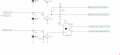
In the attached circuit (part picture grab) I am using a Toshiba Optocoupler 4 pin device, not 6 pin as shown (TinyCad doesn't have the 4-pin symbol in its library).

My circuit uses the Arduino Uno and when pin 10 goes high (logic +5V), T5 conducts, turning on the opto. This base current then in turn allows current to flow throught the Collector / Emitter and thus triggers a 3rd party device.

This does work, however; for stability and good electronic design would it be prudent to connect pin 4 of the Opto to the circuit's ground OR is that not really necessary. After all, the whole purpose of an Optocoupler is to isolate one circuit from another.

Comments appreciated and thank you.
 

Attachments

AnalogKid

Joined Aug 1, 2013
10,987
Depends on the details of the ultra-high-toppiest-most-secrety device. One way to interpret your schematic is that the opto output is trying to place a dead short across a 5 V power supply.

ak
 

Thread Starter

Andreas

Joined Jan 26, 2009
90
Depends on the details of the ultra-high-toppiest-most-secrety device. One way to interpret your schematic is that the opto output is trying to place a dead short across a 5 V power supply.

ak
That's some adjective. Did you make that up yourself ? ;-) The trigger device is from a motion capture camera and normally its BNC input gets fitted with a very simple N.O. push button switch. You tell it in software if you want a positive or negative trigger. In my case I'm merely pulling its line from hi to low.
 

AnalogKid

Joined Aug 1, 2013
10,987
An external switch is complete floating (called a dry contact), and so is the output of the opto. Should work without tying the output emitter to the "ground" on either side.

ak
 

Thread Starter

Andreas

Joined Jan 26, 2009
90
An external switch is complete floating (called a dry contact), and so is the output of the opto. Should work without tying the output emitter to the "ground" on either side.

ak
Yes, in this case it is. But then that's a passive component and in an entirely isolated condition. The reason for my orig. post came really from the point that the opto is an active component and as such I felt it may require a potential difference between the Base and Emitter within the same grounded reference for it to work reliably but clearly this is not required. Would you agree?

Cheers,
Andreas
 

philba

Joined Aug 17, 2017
959
optoisolators are used to isolate two circuits from each other. So, you don't need to connect the two grounds as that would defeat the point of an optoisolator. The phototransistor is part of your "passive component" circuit. No gnd, or other, connection is required.

Using a transistor to drive that opto is very likely overkill. Definitely if the "Nano" in you diagram is an Arduino. It could drive 2 LEDs+resistors in parallel for up to about 40 mA though I'd keep it a lot less. I'd also move the indicator LED to the other side so you know the signal got through.
 

AnalogKid

Joined Aug 1, 2013
10,987
it may require a potential difference between the Base and Emitter within the same grounded reference
That "potential difference" comes from the light from the LED with no ground reference expressed or implied. That's what makes optos so cool. The LED circuit voltages and the emitter circuit voltages can be hundreds of volts apart (depending on the device isolation rating).

ak
 

Thread Starter

Andreas

Joined Jan 26, 2009
90
optoisolators are used to isolate two circuits from each other. So, you don't need to connect the two grounds as that would defeat the point of an optoisolator. The phototransistor is part of your "passive component" circuit. No gnd, or other, connection is required.

Using a transistor to drive that opto is very likely overkill. Definitely if the "Nano" in you diagram is an Arduino. It could drive 2 LEDs+resistors in parallel for up to about 40 mA though I'd keep it a lot less. I'd also move the indicator LED to the other side so you know the signal got through.
Nice idea on removing T5, R14 and D10 and instead I have wired the anode of the opto directly to junction of R9 (via the 240 current limit resistor).
You are correct that the Nano can drive 40mA and with both Leds ON should only consume 34mA for 0.5s so we're good there.
Moving the LED to the other side has merrit but I'd like to keep that side of things completely separate and I know that the signal has got through as software capture is initiated.

Tnx for your input.
 
Top