 Facebook
 Google
 GitHub
 Linkedin
Hello everyone,
As a junior electronics student, I'm currently working on a constant current regulation using an AOP connected as a subtractor to drive a MOSFET of this type:

My concern is that I've heard that the input capacitance of the MOS (Ciss/Qg) can disrupt the regulation and cause oscillations or unstable behavior in the control loop. For your information, here is the data for the MOSFET I plan to use:

Unfortunately, I won't be able to test the schematic on a breadboard before mounting it on a PCB, even though that would be the best thing to do. I think it's possible to simulate it in simulation software, but I'd like your opinion before trying this option.
Would it be possible to have your advice/feedback on optimizing the resistor and capacitor network (placement, role, etc.) around this AOP to improve the stability (compensation, filtering, etc.) of the regulation without degrading it?
First of all, it seems to me that a resistor placed before the gate is essential, and a capacitor placed like this is often used as well:

I also saw that a snubber could be added, what does that mean?
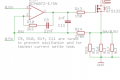
For example, I found this constant current discharge assembly online, but I don't understand what C9 and R14 are for...

If any of you have already encountered this problem or have reference schematics, I'd be grateful.
Thanks in advance for your insight!
Zebananos
As a junior electronics student, I'm currently working on a constant current regulation using an AOP connected as a subtractor to drive a MOSFET of this type:
My concern is that I've heard that the input capacitance of the MOS (Ciss/Qg) can disrupt the regulation and cause oscillations or unstable behavior in the control loop. For your information, here is the data for the MOSFET I plan to use:
Unfortunately, I won't be able to test the schematic on a breadboard before mounting it on a PCB, even though that would be the best thing to do. I think it's possible to simulate it in simulation software, but I'd like your opinion before trying this option.
Would it be possible to have your advice/feedback on optimizing the resistor and capacitor network (placement, role, etc.) around this AOP to improve the stability (compensation, filtering, etc.) of the regulation without degrading it?
First of all, it seems to me that a resistor placed before the gate is essential, and a capacitor placed like this is often used as well:
I also saw that a snubber could be added, what does that mean?
For example, I found this constant current discharge assembly online, but I don't understand what C9 and R14 are for...
If any of you have already encountered this problem or have reference schematics, I'd be grateful.
Thanks in advance for your insight!
Zebananos
Attachments
-
 19.4 KB Views: 1


