Facebook
 Google
 GitHub
 Linkedin
I have an Adafruit SoundFX board that runs on 4.5V.
There are several terminals on the board that allow sounds to be played. You simply connect a terminal to ground and it will play a sound. Generally I achieve this via a pushbutton that shorts the terminal to ground.
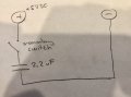
Now, for complicated reasons not worth detailing I need to close two terminals at the same time (i.e. 2 different sounds at the same time, but then the tricky part is when I release the button I need terminal 1 to release immediately while terminal 2 to release shortly AFTER (0.1 secs or so). Net, how can I device a way to close simultaneously, yet open with a small delay between the 2? Simplifying the problem: Heck may if someone can point me to a way to close a momentary switch immediately (hold close), and yet open it after a delay when "opened" (hold release).
I don't think there is voltage running through those terminals, certainly not the 4.5V circuit.... not sure how to approach this. Purely mechanical I think is out of the question as I am not aware of switches that are delayed (except a relay etc).
Is there a simple passive way to achieve this? Other alternatives?
There are several terminals on the board that allow sounds to be played. You simply connect a terminal to ground and it will play a sound. Generally I achieve this via a pushbutton that shorts the terminal to ground.
Now, for complicated reasons not worth detailing I need to close two terminals at the same time (i.e. 2 different sounds at the same time, but then the tricky part is when I release the button I need terminal 1 to release immediately while terminal 2 to release shortly AFTER (0.1 secs or so). Net, how can I device a way to close simultaneously, yet open with a small delay between the 2? Simplifying the problem: Heck may if someone can point me to a way to close a momentary switch immediately (hold close), and yet open it after a delay when "opened" (hold release).
I don't think there is voltage running through those terminals, certainly not the 4.5V circuit.... not sure how to approach this. Purely mechanical I think is out of the question as I am not aware of switches that are delayed (except a relay etc).
Is there a simple passive way to achieve this? Other alternatives?