OpAmps get very hot on PCB

Thread Starter

bluezap

Joined Oct 15, 2018
8
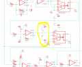
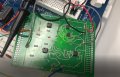
Hi, I designed, printed and soldered my first PCB. For some reason, it doesn't work and the Opamps get very hot. When I test the same circuit out on a breadboard, it works fine.
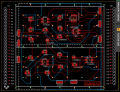
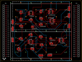
Could someone please take a look at it and see if anything is wrong, there is a route that was damaged on the right but that happened after I tested the circuit.
I have attached the schematic and pictures of the board for reference. Also, am I laying the components in the correct orientation here? the orientations of the OpAmp confuse me.

For example, how do I know the orientation of the OpAmps looking at the beveled circle on the component?

Any help would be much appreciated.
 

Attachments

Thread Starter

bluezap

Joined Oct 15, 2018
8
Would this affect my circuit if I just connected the correct pos and neg leads? I don't quite understand, sorry I'm very new to this.
 

AlbertHall

Joined Jun 4, 2014
12,345
The following from the PCB layout looks to me like you have pin 3 of MP2 connected to pin 6 of MP1 and as pin3 is the negative supply and pin 6 is the positive supply then however you connect the supply one of these chips must have the power reversed.
upload_2018-10-16_0-55-41.png
 

Thread Starter

bluezap

Joined Oct 15, 2018
8
Okay, so how would I route this to avoid the power reversal? I'm still confused, sorry. Thank you for taking the time to reply by the way, much appreciated!

I have fixed the problem on the schematic but can't figure out the routing on the brd
 

Attachments

AlbertHall

Joined Jun 4, 2014
12,345
In eagle if you click the thing that looks like an eye, top right of the toolbar, and then click a wire it will highlight everything connected to that wire. This very useful for checking the board.
 

ebp

Joined Feb 8, 2018
2,332
It is always wise for beginners to check the power and ground connections to ICs on a board with an ohmmeter before putting any parts on the board. Problems with power and ground seem to be quite common and are much more likely to cause damage than errors in signal connections.

There are two 1k resistors near the green wire on the left hand side of the board. I can't make sense of the traces. It looks like there is white ink printed over top of some of them, but it also gives the impression that the track across the board to the right of the green wire connects to the white track between the right hand ends of those two resistors. Is that actually the case or is this a four layer board?

If you can edit your schematic symbols library, I strongly recommend putting the power pins on the actual symbol or an extra sort of "dummy" section, and adding plus and minus signs. This goes a long way to avoiding accidentally connecting the power incorrectly.

I have never before seen power pins represented the way they are on your schematic.

For good all-round performance, the passive components that surround op amps should be placed physically close to the amplifier IC when reasonably possible, with occasional exceptions. You should also have power supply decoupling capacitors which MUST be placed close to the amps, though if the layout is very compact and amp packages are close together with carefully routed power and ground, one set of decoupling caps can serve two or the amplifier ICs. If the amps operate at high frequency or handle significant current, each should have its own decoupling caps. Try to make your power and ground traces wider than signal traces if you can. This somewhat improves performance and also helps to distinguish them on the PCB, which can be nice during development.
 

Thread Starter

bluezap

Joined Oct 15, 2018
8
@ebp I'm reading and trying to comprehend your response, I'll change up my work accordingly thank you!, but I changed up the routing a bit, in its general sense, does this routing look right? there seem to be no errors now.
 

Attachments

Thread Starter

bluezap

Joined Oct 15, 2018
8
@ebp, I will respond to your questions soon, sorry about that, I'm not trying to ignore your response, it's very valuable to me.
 

ebp

Joined Feb 8, 2018
2,332
No worries! The whole idea of the AAC forum is to help people learn things and solve problems. Threads often go on for several days and sometimes weeks as people take time to think about things and do experiments and the like.
 

Thread Starter

bluezap

Joined Oct 15, 2018
8
Here is another orientation for the OpAmp. Can someone please see if this routing is right? (I'm trying to get that right first)
Thank!
 

Attachments

Top