
0
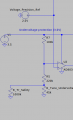
I've been trying to realize an OPAMP undervoltage protection circuit (see attachment, OPAMP voltage comparator topology).
I'm using the AD8032 2.7 V Rail-To-Rail Amplifier for this task.
In LTSPICE simulation the Voltage on the output drops to 0V (-VCC) when the input at the inverting input is over the reference voltage at the noninverting input and goes to +VCC when the input at the inverting input is below the reference. That's what is supposed to happen.
However in the real-life breadboard test circuit the voltage at the output only drops to 1.3V and not near -VCC when the voltage on the inverting input is over the reference voltage on the noninverting pin.
I'm really not an OPAMP expert. What am I doing or thinking wrong?
Thank you very much!
Attachments
-
 19.6 KB Views: 26


