Opamp gain-of-5 stability resistor

Thread Starter

oh_uh_okay

Joined Aug 24, 2025
79
In a preamp project that uses the now-obsolete AD745 opamp, the designer notes in the PHONO PREAMP section " R3 satisfies the gain-of-5 stability requirement of the AD745."
The AD745 is no longer avail, and if I do pursue this project, I may need to substitute another opamp. So how will this affect the value R3?
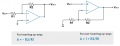
In the AD745 datasheet, Figure 22 (p6) does note Gain of 5 Follower metrics.

https://www.frc.utexas.edu/page11/files/AD745.pdf

I'm not sure "Gain of 5 Follower" is a common, important, or sensitive opamp metric?

Bottom line:
If I chose another "high-speed, FET input" opamp -- say common OPAx132 -- how might this value or R3 be tweaked ( or other passive components tweaking the AD745 ues in the phono stage above)?
 

kiroma

Joined Apr 30, 2014
119
"The internal compensation of the AD745 is optimized for higher gains, providing a much higher bandwidth and a faster slew rate. This makes the AD745 especially useful as a preamplifier where low level signals require an amplifier that provides both high amplification and wide bandwidth at these higher gains." (datasheet of the op amp)

To me it's just a technology that is optimized for amplifying signals. You need a comparable gain bandwidth product op amp. Just that.

The OPAx132 is 8 MHz of gain bandwidth product, so it's comparable. I don't know the levels of signal you're trying to amplify, but as it is audio, it's not that different from the common electric guitar or bass. I'd try it without a second thought, with the same circuit.
 

kiroma

Joined Apr 30, 2014
119
Got to see that the gain is 40 dB (of the stage). So with 20 MHz (originally), you'd have a 200 kHz bandwidth. With 8 MHz, you'll have 80 kHz. Still more than enough.
 

Ian0

Joined Aug 7, 2020
13,204
the Ad745 is a very quiet op amp, pointless for this project as it is 20dB quieter than the noise from the 47k cartridge load resistor. Just use a NE5532, which has plenty of drive so you don’t need the obsolete BUF04, and you can leave out R3 and get a more accurate RIAA a response at 20kHz, because the 5532 is unity-gain stable.

P.S. With a gain of 40dB at 50Hz, the RIAA response will take 20dB off that at 1kHz, and 20dB gain at 1kHz for a moving magnet cartridge is a bit on the mean side. 30dB or 35dB would be more like it.
 
Last edited:

Thread Starter

oh_uh_okay

Joined Aug 24, 2025
79
The OPAx132 is 8 MHz of gain bandwidth product, so it's comparable. I don't know the levels of signal you're trying to amplify, but as it is audio, it's not that different from the common electric guitar or bass. I'd try it without a second thought, with the same circuit.
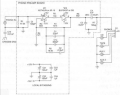
It's the phono preamp section of the project page I linked to. Here is the schematic:

So what about the value of R3 if one does use OPAx132
 

Ian0

Joined Aug 7, 2020
13,204
Zero.
it allows the gain to reach unity, which means it has a better chance of following RIAA all the way to 20kHz without the R6/R3 bodge circuit.
The downside is that it might need the rest of the values recalculating.
 

kiroma

Joined Apr 30, 2014
119
It's the phono preamp section of the project page I linked to. Here is the schematic:

So what about the value of R3 if one does use OPAx132
One way you can do it is simulating (EveryCircuit app is real time adjust) to see how you want that filter to be. R3 is there to keep the gain up to the point of stability. So in other op amps that doesn't require this gain to be met, you can have it 0 ohms, as @Ian0 said. But then the R1, R2, C1, C1a, and C2 form a filter that you probably want to tune it again after changing the op amp.
I suggest EveryCircuit because it's very fast to solve and get what you want.
https://everycircuit.com/ it does have a mobile app that you can share circuits with the community.
If you're having trouble with it, just tell me and I can tune it for you and share the circuit (and values). Just need to know what are your filter specs.
 

kiroma

Joined Apr 30, 2014
119
I went to search what a RIAA was, and I'm sorry for being so noob at this topic (I didn't think it was so low level signal and that it was so sensitive to noise), but I think that this is important to post here:

A RIAA amplifier (or phono preamplifier) is a specialized device required to play vinyl records by performing two critical functions: amplifying the extremely weak electrical signal from a turntable cartridge and correcting the frequency response to match the standard RIAA equalization curve.

During the vinyl mastering process, bass frequencies are attenuated and treble frequencies are boosted to allow for narrower grooves, reduced surface noise, and better physical durability. The RIAA amplifier reverses this process during playback, restoring the original flat frequency response and providing the necessary gain to bring the signal up to a standard line level for connection to speakers or receivers.

Having that said, you just might don't need R3, or it might be needed to reach the response you need. I guess that R3 was an obstacle the designer of that phono amplifier stumbled upon when designing the circuit, and had to adjust the other components to match to a certain degree the response needed. But that's just a guess, wish I could help you more.
 

MisterBill2

Joined Jan 23, 2018
27,896
Certainly it needs to be understood that the RIAA frequency response curve is not the same as a "flat" frequency response curve. The applications are different.

And as for a "stability resistor", that references an issue from long ago, when not all op-amps would be completely stable at all possible gain configurations. THAT ERA IS LONG PAST, at least for the past few decades.
Of course it is possible that with a poor enough assembly layout the circuit may be unstable, I suppose.
 
Last edited:

Thread Starter

oh_uh_okay

Joined Aug 24, 2025
79
Having that said, you just might don't need R3, or it might be needed to reach the response you need.
Huh?
Forget about RIAA, which is eq ... R3 is not really affecting the eq, but rather stabilizing follower GAIN. As I noted in the first post, the AD745 datasheet notes, in Fig. 22, the Gain-of-5 Follower metric ... and that it seems to be an important issue REGARDLESS of of how the AD745 is used. And that's why the value of the resistor -- at position R3, 604 ohms, in the project schematic or 2k-ohms in the datasheet -- needs to be addressed for another opamp (as necessary) .
 

Ian0

Joined Aug 7, 2020
13,204
A flat frequency response doesn’t work, because the bass grooves become too big, be difficult for the stylus to track and take up too much sPace on the precious vinyl.
The obvious alternative, a 20dB/decade slope overdoes it, and leaves the bass signals needing too much amplifications. There were scores of attempts at finding the perfect EQ, and the one they decided upon was RIAAs, which has a 20dB slope above 2122Hz, a flat section around 1kHz and another 20dB per decade slope between 50Hz and 500Hz.
That reduces the size of the bass grooves but not too much, and doesn’t require too much amplifications of the bass.

If requires a non-inverting op-amp circuit to implement it, and has the annoying property that the gain should call continuously above 2122Hz, but a non-inverting op-amp has a minimum gain of 1.

With 50dB of gain at 50Hz, the required gain reaches unity at 20kHz and then you can make the argument that it doesn’t really have to keep falling beyond that, because you can’t hear it.
 
Last edited:

kiroma

Joined Apr 30, 2014
119
Huh?
Forget about RIAA, which is eq ... R3 is not really affecting the eq, but rather stabilizing follower GAIN. As I noted in the first post, the AD745 datasheet notes, in Fig. 22, the Gain-of-5 Follower metric ... and that it seems to be an important issue REGARDLESS of of how the AD745 is used. And that's why the value of the resistor -- at position R3, 604 ohms, in the project schematic or 2k-ohms in the datasheet -- needs to be addressed for another opamp (as necessary) .
It stabilizes the gain, but it also affects the filter, so the designer had to account for it.
You can put that filter into Laplace domain and get the transfer function and see what are the frequencies that break the Bode plot, it would tell what these R and C are doing. And certainly, R3 would affect it not just by a sole gain in DC.
 

AnalogKid

Joined Aug 1, 2013
12,221
With 8 MHz, you'll have 80 kHz. Still more than enough.
80 kHz is only two octaves above the magical 20 kHz bandwidth value, and one octave or less above the actual signal bandwidth. If you are sweating tenths of a dB, there will be a slight rolloff and some phase shifts within the signal bandwidth.

ak
 

Thread Starter

oh_uh_okay

Joined Aug 24, 2025
79
Hey folks ... many of you are getting off-topic and confusing the original query.

If you don't know or don't care about the original topic -- "Opamp gain-of-5 stability resistor"-- then please don't embarrass yourselves further by engaging in idle, generic, unrelated and immature diversions.
 

kiroma

Joined Apr 30, 2014
119
80 kHz is only two octaves above the magical 20 kHz bandwidth value, and one octave or less above the actual signal bandwidth. If you are sweating tenths of a dB, there will be a slight rolloff and some phase shifts within the signal bandwidth.

ak
You're right. I never thought about that. That's 0.264 dB of attenuation at 20 kHz. I think you can bump a bit in the filter to compensate this loss though.
 

kiroma

Joined Apr 30, 2014
119
Hey folks ... many of you are getting off-topic and confusing the original query.

If you don't know or don't care about the original topic -- "Opamp gain-of-5 stability resistor"-- then please don't embarrass yourselves further by engaging in idle, generic, unrelated and immature diversions.
Maybe you didn't get what I tried to say. You have to redesign the filter if you want to get rid of R3. Otherwise, you can just stick with R3, as this filter already works.
An analogy would be this: imagine you have some circuit that requires a certain condition to reach stability. Then, you can remove this condition by changing a part. So, what you got is that you don't need to meet that stability anymore and thus the circuit still works.
The filter works because it wasn't designed for another op amp and suddenly you need it for this old op amp. It's the other way around, which doesn't exclude or require a modification.
 

panic mode

Joined Oct 10, 2011
5,144
I may need to substitute another opamp. So how will this affect the value R3?
you do not change that value. with open loop (R3=infinity) OpAmp gain is huge. but adding resistors constraints that gain to some lower, fixed value.
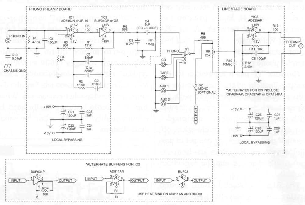
this is how gain is calculated:
1785346693229.png


gain in image 22 (p6 of datasheet) is 5 because:
a) this is noninverting amp (signal is on input+)
b) resistor ratio is 2000Ohm/500 Ohm = 4 so total gain is A= 1+4=5
1785346682327.png


in the project you linked, gain is controlled by ratio of resistors R3 and R4. their ratio is 600/120=5 so overal gain is 1+5=6 (and not 5), likely just a typo. And after all, this is just an audio amp so gain 5 or 6 makes little difference. If this was an instrumentation circuit, such difference in gain would be catastrophic, but in audio applications you have a volume knob and adjust it as you please. So if the signal is too high (for whatever is after this stage) you can choose to reduce R3. If it is too low and you need more gain, you can increase R3. if you want to follow that project as is, stick with the R3 value they used. Buffer is just buffer so it can be ignored since gain = 1. rest of the parts in the feedback loop (R1,C1,C1a,R2,C2) are shaping frequency response.
1785346963074.png
 
Last edited:
Top