OPAMP Output Clipped

Thread Starter

Engineer_tech

Joined Sep 19, 2014
31
Hello to All,

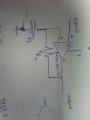
I have an OPamp setup in a non inverting configuration for the amplification of a very small signal.The Amp has a gain of 70.
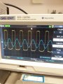
the output of op-amp is 200mV p-p sine wave signal but is clipped from one side.I am not sure what could be the reason and how can i fix to the proper sine wave.
here is a bit of description to give you an idea.
I am using OPa 211 op-amp in non inverting configuration with feedback resistor value of 70k. The input of an opamp is a small signal(i cannot scope it as its less than few mv) coming from a coil induced by another coil.
P.S i have made the circuit on Bread Board for testing and i didn't connect any capacitor yet to filter the output

Please share your quick suggestions
Thanks
 

wayneh

Joined Sep 9, 2010
18,100
Without looking I am guessing that one of your inputs or outputs is too close to one of the power rails. Take a look at the common mode input range in the data sheet.
 

#12

Joined Nov 30, 2010
18,224
Without looking, I am guessing you didn't even use 2 power supplies, you have no resistor from the inverting input to common, your common point isn't centered, etc.

This is why posting a schematic is a requirement for this kind of question.
 

Thread Starter

Engineer_tech

Joined Sep 19, 2014
31
Without looking, I am guessing you didn't even use 2 power supplies, you have no resistor from the inverting input to common, your common point isn't centered, etc.

This is why posting a schematic is a requirement for this kind of question.
well i am using two power supplies -Vee and +Vcc .
here is the attached picture of the input vs output
 

Attachments

Thread Starter

Engineer_tech

Joined Sep 19, 2014
31
Unknown power voltages, unknown resistance to ground, unknown input circuit...
I give up.
i apologize for not providing enough information on the schematics circuit
here is the description:
Vee=-5v
Vcc=5V
feedback resistor: 70K
resistor to ground :1K
I am sorry i am a newbie a still trying to pose my question in a way other can understand.
 

bertus

Joined Apr 5, 2008
22,913
Hello,

With a feedback resistor of 70 K and a resistor of 1 K to ground the gain is (70 K + 1 K) / 1 K = 71 times.
71 times the 200 mV = 14.2 Volts, what not can happen as your total voltage on the opamp is 10 Volts.

Bertus

PS what opamp are you using.
Many opamps will not work rail to rail.
 

Thread Starter

Engineer_tech

Joined Sep 19, 2014
31
Hello,

With a feedback resistor of 70 K and a resistor of 1 K to ground the gain is (70 K + 1 K) / 1 K = 71 times.
71 times the 200 mV = 14.2 Volts, what not can happen as your total voltage on the opamp is 10 Volts.

Bertus

PS what opamp are you using.
Many opamps will not work rail to rail.
I am using 0pa 211 from TI.actually the output voltage os 200mv. The input source is an output voltage of a coil been driven by function generator.After using Amp with a gain of 70 i get an output signal of 400mV
 

JohnInTX

Joined Jun 26, 2012
4,787
You don't show what you did with the SHUTDOWN pin8. The datasheet pp15 says it has to be connected and not left floating.
Not sure about the vertical deflection settings in your picture of the scope. I see an input of 2Vp-p on CH2 not 200mv. CH1 says 200mv and it knows its a 10x probe (according to the readout) but if it were off a factor of 10, you'd be close to clipping at the rails. AC coupling would account for the baseline shift. Sometimes, my scope gets confused in that way - just thinkin'.

Thinkin' more, with AC coupling, the output signal could be railed already and you are just seeing some ripple on the output.
 
Last edited:

Thread Starter

Engineer_tech

Joined Sep 19, 2014
31
Hello,

Can you make a drawing how the function generator, coil and opamp-circuit are connected?

Bertus
I am sorry i wont have the drawing of the coil and how its connected inside, but i was given a fork kind of thing which has to be driven from one side with fucntion generator the fork vibrates and induce voltage and the other side of the coil .I have no clue of this concept and how it works
The output of the other coil is small and i need to amplify it in order to scope it.
so that what i did i connected the output lines of the fork to the input of amp and tried to amplify it all i got was a few hundred mili volts signal with clipped ends i need to remove the clipped ends of the sine wave.
 

Thread Starter

Engineer_tech

Joined Sep 19, 2014
31
You don't show what you did with the SHUTDOWN pin8. The datasheet pp15 says it has to be connected and not left floating.
Not sure about the vertical deflection settings in your picture of the scope. I see an input of 2Vp-p on CH2 not 200mv. CH1 says 200mv and it knows its a 10x probe (according to the readout) but if it were off a factor of 10, you'd be close to clipping at the rails. AC coupling would account for the baseline shift. Sometimes, my scope gets confused in that way - just thinkin'.

Thinkin' more, with AC coupling, the output signal could be railed already and you are just seeing some ripple on the output.
well i am using the s0-8 package and on datasheet Page 3 (first IC) says it has to be NC that is why i left it floating.
 
Top