 Facebook
 Google
 GitHub
 Linkedin
Hi all,
I am tinkering with some LM358 opamps and voltage clamp diodes. I am not trying to accomplish anything, just tinkering/learning here. So here goes:
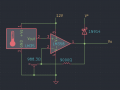
I have a LM358 fed by the output of a LM35. The opamp gain is roughly 10x, so at room temperature, 21 degrees Celsius is 0.21V coming out of the LM35 and 2.1V at the opamp output. Increasing the temperature of the LM35 brings the output up in a linear fashion. I add a diode to the output with the cathode side on a voltage rail thinking that as the opamp output increases past the forward voltage of the diode, it will eventually conduct to the voltage rail and "clamp" the opamp output at that voltage (increasing the current drawn from the opamp output which I know is not a good idea...Just tinkering here). So say the diode's cathode is on a 3.3V LDO regulator output, the Vf for a 1N914 is somewhere in the 400mV to 600mV range depending on temperature and current so as the output passes (3.3V + Vf, which is say 400mV = 3.7V) I figured the voltage wouldn't surpass that level.
What I find is that the voltage on the output of the LDO regulator increases along with it and I'm not sure I understand why. Touching a soldering iron tip to the LM35 to heat it up briefly (I have tons of these things, so if it dies it's a sacrifice I'm willing to make) will send the 3V3 rail up past 4.5 to 5V or more.
Why no clamp? I know sometimes there are resistors with Overvoltage protection diodes to limit excess current from the opamp but I would imagine that decreasing the current would make it harder for the diode to conduct and probably increase it's Vf threshold. Does it have something to do with the sink/source of the LDO regulator maybe?
I am tinkering with some LM358 opamps and voltage clamp diodes. I am not trying to accomplish anything, just tinkering/learning here. So here goes:
I have a LM358 fed by the output of a LM35. The opamp gain is roughly 10x, so at room temperature, 21 degrees Celsius is 0.21V coming out of the LM35 and 2.1V at the opamp output. Increasing the temperature of the LM35 brings the output up in a linear fashion. I add a diode to the output with the cathode side on a voltage rail thinking that as the opamp output increases past the forward voltage of the diode, it will eventually conduct to the voltage rail and "clamp" the opamp output at that voltage (increasing the current drawn from the opamp output which I know is not a good idea...Just tinkering here). So say the diode's cathode is on a 3.3V LDO regulator output, the Vf for a 1N914 is somewhere in the 400mV to 600mV range depending on temperature and current so as the output passes (3.3V + Vf, which is say 400mV = 3.7V) I figured the voltage wouldn't surpass that level.
What I find is that the voltage on the output of the LDO regulator increases along with it and I'm not sure I understand why. Touching a soldering iron tip to the LM35 to heat it up briefly (I have tons of these things, so if it dies it's a sacrifice I'm willing to make) will send the 3V3 rail up past 4.5 to 5V or more.
Why no clamp? I know sometimes there are resistors with Overvoltage protection diodes to limit excess current from the opamp but I would imagine that decreasing the current would make it harder for the diode to conduct and probably increase it's Vf threshold. Does it have something to do with the sink/source of the LDO regulator maybe?
Attachments
-
 27.9 KB Views: 28
 -
 140.7 KB Views: 27


