Opamp mains noise [RESOLVED]

Status
Not open for further replies.

Thread Starter

Alex Cristian R

Joined Feb 16, 2019
37
@Audioguru again , the buzzing loudness seemed to be the same same at 100mA, i have noticed only a change in tone of the buzzing.

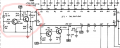
@MisterBill2 could that cause the buzzing? The power amplifier is the only load for that supply line, i can't see anything else connected to that line.
 

Audioguru again

Joined Oct 21, 2019
6,826
The main filter capacitors C1 and C2 are not doing their job of filtering the sawtooth waveform from the rectifiers probably because the capacitors are old and need replacement.
You are restoring an old amplifier. Some people replace all the electrolytic capacitors on an old amplifier to make it sound like new.
 

MisterBill2

Joined Jan 23, 2018
27,600
Often times the failure mode is a greatly increased internal series resistance, which reduces the effective capacitance, which in turn tends to cause exactly the symptom we see. But before replacing those capacitors, try disconnecting them and cleaning the screw terminals, and then reconnect them and see if that made a difference. I suggest that because sometimes aluminum builds up an insulating oxide coating, which also adds a series resistance. Cheap and easy to fix, if that is the problem.
 

Thread Starter

Alex Cristian R

Joined Feb 16, 2019
37
@MisterBill2, @Audioguru again , @crutschow I have finally replaced the caps but unfortunately there is no improvement.

Would higher rating caps do a better job? Or is this not the problem?
 

Attachments

Thread Starter

Alex Cristian R

Joined Feb 16, 2019
37
Your Falcon (no-name-brand) capacitors were made in the 43rd week of 1980, 43 years old! Maybe too unknown and too old to be good filters.
Well, now i have replaced them and the problem still persists. The black ones in the image are brand new caps. They are Jamicon, couldn't find any better brand in the shop.
 
Last edited:

Thread Starter

Alex Cristian R

Joined Feb 16, 2019
37
Taking a better look, the new caps seem to be effective. I have noticed that on volume set to zero there is less buzzing than before. Now only as i increase the volume the buzzing becomes stronger.

I have also noticed that when i hook the oscilloscope probe on the amplifier power line the buzzing becomes stronger. That means that my previous measurements could have been wrong.
 

MisterBill2

Joined Jan 23, 2018
27,600
Given the waveform that we saw before, it still tells me that something is drawing excessive current. BUT in addition, it seems that at least some of the buzz is being introduced upstream of the volume control.
 

Thread Starter

Alex Cristian R

Joined Feb 16, 2019
37
I have finally managed to clean all the IC pins, cable connectors and contacts. This got the organ to behave even more randomly than before:
- Sometimes the Harpsicord and Piano effects would work fine, sometimes partially, sometimes would create loud pops, sometimes would do nothing.
- Sometimes the BASS VOLUME (RB72 - top right part of schematic near the external input) would not respond to adjustments and the volume of this line would be at maximum. I have checked the pot and it's fine, also replacing it made no difference.
- Notes or entire octaves would randomly not play at all. They would play for some time, then stop and, then come back again.
- The RHYTHMS & AUTOMATIC SECTION is never affected, always working fine!!!
- Powering on and off multiple times seem to change what problems show up!

@MisterBill2 As I have cleaned the contacts probably more current is drawn by some faulty components. I don't really know how to find what part of the circuit is drawing too much current.

I have replaced all the caps on the power supply and the voltage regulators. (Apparently made no difference)
 

MisterBill2

Joined Jan 23, 2018
27,600
What the situation appears to be is that there are still, and even more than before, some intermittent connections in the system. And what is certainly true is that fixing them is a challenge. On occasion, consulting the circuit schematic can assist in determining which connectors would be the most likely suspects.
And what the new problems do show is that there are problems in the connections area more than failed components.
 

Thread Starter

Alex Cristian R

Joined Feb 16, 2019
37
@MisterBill2 , @Audioguru again , @crutschow
I the past week i have removed all sockets and soldered all IC components directly to the PCB, also removed all PCB connectors and soldered the wires directly on the PCB. This seems to remove some more noise which is good. Checked all connections for continuity and all seem fine.

A problem still remains: all the keys stop working at once or just some of them. When i power up the organ (from cold) the keys work for a few seconds and then they stop working, they come back again after a few seconds and they stop working again after a few seconds. Some times whey would just work with no problem after some time if i keep the organ powered, some times they still won't work.

I have made some measurements and found some differences on the RESET pins of TMS3615. The RESET OUT frequency halves for each IC in the chain, IC3 on HIGH 37 NOTES having the highest frequency. They are all powered and receive correct clock signal.

On the LOW 24 NOTES GENERATOR:
- IC1, IC2, IC3 - pin 16(RESET IN) , pin 12 (RESET OUT) measured 40mV DC.
On the HIGH 37 NOTES GENERATOR:
- IC1 pin16, pin 12 and IC2 pin 16 measured 40mV DC.
- IC2 pin12 and IC3 pin16, pin 12 measured 280mV DC!!!

I believe the RESET voltage should have been the same for all ICs. That made me think that probably IC2 on the HIGH 37 NOTES GENERATOR was faulty since it had 280mV instead of 40mV on pin 12 (RESET OUT) and causing the other ICs to not operate correctly.
 

Attachments

MisterBill2

Joined Jan 23, 2018
27,600
To find a component that is drawing too much current and overheating a bit one could use a thermal camera of some sort. THat would reveal some parts warmer than the rest, which could be useful. But there may also be poor connections causing different portions to fail a bit. That search is tedious but not difficult, because it lnvolves wiggling connections a bit while listening for noise That can be rather boring and possibly challenging, but it can also locate the problem.
 

LadySpark

Joined Feb 7, 2024
194
@MisterBill2 , @Audioguru again , @crutschow


I have made some measurements and found some differences on the RESET pins of TMS3615. The RESET OUT frequency halves for each IC in the chain, IC3 on HIGH 37 NOTES having the highest frequency. They are all powered and receive correct clock signal.

On the LOW 24 NOTES GENERATOR:
- IC1, IC2, IC3 - pin 16(RESET IN) , pin 12 (RESET OUT) measured 40mV DC.
On the HIGH 37 NOTES GENERATOR:
- IC1 pin16, pin 12 and IC2 pin 16 measured 40mV DC.
- IC2 pin12 and IC3 pin16, pin 12 measured 280mV DC!!!

I believe the RESET voltage should have been the same for all ICs. That made me think that probably IC2 on the HIGH 37 NOTES GENERATOR was faulty since it had 280mV instead of 40mV on pin 12 (RESET OUT) and causing the other ICs to not operate correctly.
no. its ok. On the lower 26 notes generator, it does not have IC2 pin 12 and IC3 pin16 connected together. That is why you are reading 280mv on the end connections.

What you have to do is see if the signals are there and where it stops in circuit when it doesn't work. It could be an op amp buffer in the filters and tab switch pcb that started kind of working after heating it up.

Its better to pick at things one at a time and divide and conquer the circuit.
 
Status
Not open for further replies.
Top