OPA340 Open Loop Gain

LvW

Joined Jun 13, 2013
2,027
Thank you LvW,

For the Bode Plot in the post #17, I have a phase margin of 220º correct? So it should be very stable.
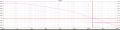
No - when the gain crosses the 0dB line (at app. 100kHz) the phase is also zero.
As you have plotted the open-loop gain Aol, the phase margin would be zero (stability limit) for 100% feedback (unity-gain Acl).
For less feedback 8higher closed-loop gain Acl) , the loop gain will approach zero for a smaller frequency - and the phase shift will be not a the stability limit.
 
Last edited:

Thread Starter

waulu

Joined Dec 23, 2016
62
Thank you LvW and ericgibbs,

I'm trying to apply the theory but it's complicated. The Analog Engineer's Calculator has a tool to calculate the values of a resistor and a capacitor for an RC filter. This is valid for a unity gain buffer when driving an ADC.

Capture1.PNG

They suggest an R between 47k and 376k with a capacitor equal to 510p.

I know that the RC filter will insert a pole between 6.6 kHz and 829 Hz. From the open loop gain I can clearly see that's not good, it means that it will cross the closed loop unity gain at -40dB/dec. Is this correct?

For example with R=47k and C=510p,

Capture.PNG

The phase margin is 1.5 Hz.

Best regards,
 
Last edited:

Thread Starter

waulu

Joined Dec 23, 2016
62
hi w,
This is what I see, you must use the Phase plot line at 0dB.
E
I will run your RC filter, post what I find.
Hi ericgibbs,

Thank you for staying with me.

I am taking some time to understand it. But let's check very quickly if I understood it correctly.

The phase margin is

- In the case of non inverter, phase(at 0 dB) - (-180º)
- In the case of inverter, phase (0 dB) - 0º

So in my case, the phase at 0 dB, is almost 0º, right? So the the phase margin is 0º - 0º = 0º

Best regards,
 

LvW

Joined Jun 13, 2013
2,027
@waulu - your understanding of stability, open-loop gain and phase margin is not correct.
All these points concern an amplifier with feedback only!!
That means: The filter circuit which is connected to the amplifier has nothing to do with these considerations - as long as the filter is not part of the feedback loop.
The stability problems concern the closed feedback loop - but the check of the stability properties is performed for the open loop.
Since you have 100% feedback - the loop gain (gain of the complete loop when it is open!) is identical to the open-loop gain Aol of the opamp only! So you have to check the phase shift at the frequency where the Aol magnitude crosses the 0dB-line.
This gives you the phase margin for the closed-loop system.

Example: The gain function Aol as plotted by Eric gives you a margin of 0 deg (at 100kHz) . This result is surprising because - according to the OPA340 datasheet - this device is unity-gain stable.
The reason is as follows: The opamp (without signal feedback) was loaded with an R-C filter. This gives you a wrong picture (and wrong results) because - as far as I understood your problem description - in reality, it is the unity gain amplifier which is loaded with RC elements. You must NOT load the opamp (without signal fedback) if you want to check if the opamp with feedback will be stable or not.
 
Last edited:

Thread Starter

waulu

Joined Dec 23, 2016
62
@waulu - your understanding of stability, open-loop gain and phase margin is not correct.
All these points concern an amplifier with feedback only!!
That means: The filter circuit which is connected to the amolifier has nothing to do with these considerations - as long as the filter is not part of the feedback loop.
The stability problems concernthe closed feedback loop - but the check of the stability properties is performed for the open loop.
Since you have 100% feedback - the loop gain (gain of the complete loop when it is open!) is identical to the open-loop gain Aol of the opamp only! So you have to check the phase shift at the frequency where the Aol magnitude crosses the 0dB-line.
This gives you the phase margin for the closed-loop system.
Example: The gain function Aol as plotted by Eric gives you a margin of 0 deg (at 100kHz) - hence, this opamp is not unity-gain stable and it canno be used as a unity-gain buffer.
Hi LvW,

Thank you for your reply.

I tried to add the RC filter and make that kind of analysis because I read this documents, PA-001 Optimize_SAR_converter_design REV b.pdf, and in the page 34 they added a RC filter and they modified the Bode plot with a pole and zero (I don't know from where it comes the zero) .

Ok it will be never stable, I think I understand that. I can already conclude something =) Unless that I modify the closed loop to some other gain.

Best regards,
 

Attachments

LvW

Joined Jun 13, 2013
2,027
Please, read my update....the opamp will be stable!! But you must not load the opamp under open-loop conditions.

I must admit that I do not understand the following sentence within the referenced paper:
"The open-loop gain (AOL) of the op amp will be modified by a pole present
from the open loop resistance plus RFLT|CFLT, and then cancled by a zero
from the RFLT|CFLT."


For my opinion this is false!
If the RC-filter is connected to the output of a unity-gain buffer it is NOT correct to check the stability of this buffer with the RC filter being connected to the opamp when it is analyzed WITHOUT feedback. This would be only true when the RC filter is part of the fedback loop, but - as far as I can see - this is not the case.
 
Last edited:

Thread Starter

waulu

Joined Dec 23, 2016
62
Please, read my update....the opamp will be stable!! But you must not load the opamp under open-loop conditions.
My mistake was to load amp op with the RC filter during the plot of the open loop gain. So the correct graph would be,


Capture.PNG

Phase margin = phase (@0dB) - 0ºC = 76.4º

So it's very stable. I hope now it's correct.
My next step would be to evaluate the effect of an RC filter on the amp op. I thought it would be possible because Texas did it in the document PA-001 Optimize_SAR_converter_design REV b.pdf. They add the pole and the zero (no ideia from where it comes) from the RC filter to the bode plot of the open loop gain.

If it's not too much, would you indicate the way to do that kind of analysis?

Best regards,
 

Thread Starter

waulu

Joined Dec 23, 2016
62
For my opinion this is false!
If the RC-filter is connected to the output of a unity-gain buffer it is NOT correct to check the stability of this buffer with the RC filter being connected to the opamp when it is analyzed WITHOUT feedback. This would be only true when the RC filter is part of the fedback loop, but - as far as I can see - this is not the case.
Thank you, I will consider that papper not valid.

hi waulu,
Have you seen this series of TI videos.?
Is this project a College assignment.?

E
Hi ericgibbs,

Yes, I saw the videos, I post one of the videos in the first post. They are very interesting but they don't do a theoretical analysis with the RC filter. They rather simulate the amp op, RC filter and the ADC. I am interested in doing it too, but first I want to understand the theory and try to correlate it with a real component.

No, all this started because my company had designed a circuit and made some test but they didn't have any documentation. They just asked me to write documentation, nothing very complicated.

For some reason, I got interested in this subject. So right now this is for myself. I believe too that one of the best ways to learn electronics is to characterize the system and if possible the components. Just for fun and it can be useful in the future too I guess.

I don't have a good reason, I will keep studying this subject while I have an interest in it.

Best regards,
 

LvW

Joined Jun 13, 2013
2,027
Phase margin = phase (@0dB) - 0ºC = 76.4º

So it's very stable. I hope now it's correct.
My next step would be to evaluate the effect of an RC filter on the amp op. I thought it would be possible because Texas did it in the document PA-001 Optimize_SAR_converter_design REV b.pdf. They add the pole and the zero (no ideia from where it comes) from the RC filter to the bode plot of the open loop gain.

If it's not too much, would you indicate the way to do that kind of analysis?

Best regards,
Yes - the mentioned margin is in full accordance with the OPA340 data sheet.
Regarding your question: The RC filter will have practically no effect on the opamp output.
Because of 100% feedback, the opamp (unity-gain buffer) has an output resistance of nearly zero ohms.
You can assume that it behaves like an ideal signal voltage source .
(The quoted sentence from the document is irrelevant because - as I have mentioned - they have assumed that the filter would be part of the feedback loop. Only in this case, it would produce a zero)

Question: What do you mean with " If it's not too much, would you indicate the way to do that kind of analysis? "
 

Thread Starter

waulu

Joined Dec 23, 2016
62
Question: What do you mean with " If it's not too much, would you indicate the way to do that kind of analysis? "
Hi LvW,

I meant, How should I analyse the amp op with the RC filter? But I think you already answered it. Now I have to think.

Thank you very much

hi w,
If you have not already seen this link, it should help with your research.

https://www.ti.com/design-resources/design-tools-simulation/filter-designer.html

E.
bonne chance dans vos études
Bonjour ericgibbs,

Thank you, I didn't know that tool. And I checked the video you posted before, I thought I had seen that one but not. I already saw a lot of videos from Texas so I got confuse.

Thank you very much

So now it's time to think about all of this.

Best regards,
 

LvW

Joined Jun 13, 2013
2,027
. Now I have to think.
................
Thank you very much
...............
t. I already saw a lot of videos from Texas so I got confuse.
...............
So now it's time to think about all of this.
Yes - that`s a good idea. Too much information from different sources can be really confusing.
And - perhaps I am a bit "oldfashioned" - but I do not like videos for introducing basics.
For my opinion - a good textbook is still the best knowledge source.
As you have seen - even some notes from companies like TI can contain some errors. So - do not blindly trust any written statements.
Instead, try to understand all the stuff (circuits and formulas).
Good luck and do not hesitate to ask again..
 
Top