Op amp output voltage is limited below expected value in current source

Thread Starter

jpborunda

Joined Apr 9, 2014
55
Hello everyone. I made a current source/sink circuit with the help of a lot of you.
Now I'm testing it, and at first it appeared it worked ok, but now I've found some unexpected behavior.

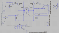
The circuit is a classic op amp + transistor current sink, and it has an H Bridge to alternate the polarity of the current PULSES through the resistor which represents my load. The H bridge has been tested previously and it is working correctly .

The current sink is made in a way that the voltage at Vin(+) of the op amp creates the desired current in Rsense. This is true because ideally, Vin(+) = Vin(-). Thus, I_rsense = Vin(+)/Rsense. Since Rsense is 10 Ohms, I'm using an input voltage range from 0.2V to 1 V to get 20mA to 100mA.

When I apply say 0.5V, I get the desired Voltage drop at the load, hence the current, since I know Rload's value (been testing with 100Ohm for RLOAD) . HOWEVER, as I increase the voltage at the op amp's input (0.5V - 0.7V), Im getting a bigger error for the expected voltage drop at the load, then when I reach 0.8V the voltage drop at Rload reaches a maximum value and remains the same, regardless of going up to 1V, even 1.5V at the input.

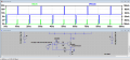
With an oscilloscope I saw that the op amp's output reaches a maximum value of 920mV aprox when applying 0.8V, and remains the same for bigger inputs.

I'm not sure what is limiting the op amps output. the op amp is an LM324n, with +5V and GND as supplies. I am aware that regular op amps don't go as high as the rail, but less than 1V is way below.

The shape of the signal is correct, it doesn't look clipped or something, its just of less amplitude, if that makes any sense...

If anybody has experienced this before, please I would appreciate any help. Muchas Gracias!
 

Attachments

Thread Starter

jpborunda

Joined Apr 9, 2014
55
Ok here's the schematic. It works in the simulation, but the behavior that I described happens whit the actual built circuit.

Basically, the input of the op amp determines the current pulse through RLOAD, so if I apply a 0.5V in the positive input, I get a current through Rsense of 50mA. Therefore, I would get that approximate current through Rload, and since Rload is 100Ohm, its voltage drop would be 5V. (This is how Im checking that the current source is working, it gives correct voltage drops up to 70~80mA desired current. After that, the voltage drop at Rsense remained the same, regardless of me increasing the +input voltage.

Because of that, I checked the op amp output, and yes, it is being "limited'' to a max value when going higher than 0.8V at the input. Im the simulation, I noticed that if I increase the VCC for the opamp to +9V, the output also increases. Does this mean that VCC = + 5V is not enough for this particular case? Also, what would happen if I remove the resistor that goes from the op amp output to the base of the transistor?

Hope I explained the situation better. Thanks a lot.
 

Attachments

crutschow

Joined Mar 14, 2008
34,285
It's not the op amp. It's that the circuit is saturating at the maximum current you are observing. If you look at the voltage drop across the collector-emitter of Q1, (click on the collector and ,while holding the mouse button down, move to the emitter and then release the button) you can observe this voltage going to a low value (few tenths of a volt) when the current maximum occurs.

So some things to increase the maximum current are:
Increase V1
Reduce the value of R8
Reduce the load resistor value

Also note that you may need to increase the drive voltage to Q4 and Q5 since the Q1 collector voltage reduces the base drive to those transistors.
 

Thread Starter

jpborunda

Joined Apr 9, 2014
55
I cant seem to obtain the behavior that you described. Q1 collector-emmiter voltage looks like almost 4V in the simulation. That is for the max current 0f 100mA, applying 1V at the +input. Attached is the voltage that I'm getting. Am I doing something wrong??

Meanwhile, Im gonna try and use a lower value of R8 to see if it is enough to get to the max current.

Thanks a lot!
 

Attachments

Thread Starter

jpborunda

Joined Apr 9, 2014
55
Oh OK sorry for the mistake, now I see what you where refering to. I tried lowering R8 to 5.6 Ohms and even 1 Ohm, it did help, as now it reaches a max voltage drop of a little more than 8.5V per pulse, But still didn't reach the 10V for a 100mA current.. Also, increasing V1 to 25 volts didn't seem to make a difference. I'm not exactly sure what to try next.
Thank you! I'll keep thinking about it
 

crutschow

Joined Mar 14, 2008
34,285
If I change Q1 to a logic level MOSFET, could that be a quick fix?
No. How would that prevent Q1 from saturating?

Below is my sim of your circuit slightly modified. I changed the transistors to ones I had models of. I also put static control voltages on the bridge so I could just look at the simulation of the current limit without the bridge switching (which should have no effect on the current limit value). As you can see with an input (Vlimit) of about 1.8V the load current goes to nearly 180mA where it saturates (Vce drops to a fraction of a volt). I'm not sure why you are seeing less current unless the transistors you are using have a significantly lower current rating.

Current Limit.gif
 

Thread Starter

jpborunda

Joined Apr 9, 2014
55
Thank you guys. Actually, I just tested the current sink without the h bridge at all, and I do get the expected voltage drop at the load for up to 100mA.
So Im thinking maybe the problem is in the Hbridge, I'm gonna try what ronv said and lower the base resistor for them, or if I have the chance, try and get some with a higher gain.

I'm not sure how does the gain affect though, is it because there might not be enough base current to saturate the transistor?
I'll report back after I tested the changes.
 

ronv

Joined Nov 12, 2008
3,770
Yes. At 100 ma there is a 1 volt drop across the 10 ohm, some drop Vce of the 2N3439 and the Vbe of the 13007. So the base drive may only be 3 ma or so. The 2N3439 may have the same problem as the 358 can only pull up to about 3.5 volts. So you might want a little smaller resistor in the base there as well.
 

Thread Starter

jpborunda

Joined Apr 9, 2014
55
Hello guys, JP here. I'm happy to tell you that the circuit is now working as desired. I changed the resistors as Ronv suggested, both at the output op amp, and for the ones driving the bridge transistors, using: Rb = (Vbb-Vbe)/(Ic/10) = 430 Ohm, so I went with some 330 Ohm resistors I had available. The max current is limited now for 15mA max from the digital pin output instead of 5mA, and the current source now works up to 100mA. Thanks a lot!!!!!!!!!!!!!!!

Let me ask just one more thing, the transistors I chose are rated for high voltages, 300 V is the breakdown voltage of the MJE350. As I look at it, increasing the voltage source (V1) shouldn't have any effect, other than giving the current source a wider range of operation correct? I'm gonna vary the RLOAD to see if the current source does its job, but I wanted to get your opinion on the subject, what if I increase the Vsource to like 100V, (Im aware of the power thats going to be generated, for the resistors and such), would there be an immediate fail I'm not seeing?

Thank you so much, 10xbetter than most 'teachers' I had at school!
 

ronv

Joined Nov 12, 2008
3,770
The only problem I see is the 1k resistor in the base of the top transistors. The power will be almost 10 watts in those at 100 volts.
Actually it is pretty high now. :)
 
Top