Facebook
 Google
 GitHub
 Linkedin
Hi Guys,
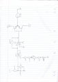
I reasonably new to the circuit design and I have recently built a LM741 motor controller configured in the inverting summing mode. Essentially I am using a temperature sensor as a reference on V1 and then I have a resistor/potentiometer divider network set up on V2 which gives a temperature set point control between 18 to 30 degrees Celsius. The set point range has a voltage from -2.91 to -3.03 volts with the temperature sensor outputting 2.97 volts at 24 degrees Celsius.
The output stage is BJT push pull class B configuration.
I used the following transfer function to determine the output voltages Vout = -Rf/R(V1 + V2)
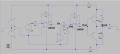
What I wanted to acheive was only +/- 6 volts out worse case and by that I mean if the temp sensor was reading 24 degrees (2.97 volts) and the set point was at either end of the extreme of the potentiometer the max would be 6 volts out. To achieve this the gain is set to 100 via R1 and R2 being set at 6k8 and connected to the inverting input, The non-inverting connected to common and Rf 680K.
I have set this up in the simulator LTSpice and everything seems to be working fine with +/- 6 volts when in the conditions just mentioned, however when I implemented this on the breadboard and after I begin to adjust the set point control at the 0.6 volt mark when the transistor begins to switch on the motor is violently switched forward and reverse continually and I can not for the life of me understand why. The output transistors are BD 139 and 140 respectively and the Op-Amp is being supplied with +/- 12 volts DC.
Would appreciate any advice or things I may be able to try.
Regardd
Dan
I reasonably new to the circuit design and I have recently built a LM741 motor controller configured in the inverting summing mode. Essentially I am using a temperature sensor as a reference on V1 and then I have a resistor/potentiometer divider network set up on V2 which gives a temperature set point control between 18 to 30 degrees Celsius. The set point range has a voltage from -2.91 to -3.03 volts with the temperature sensor outputting 2.97 volts at 24 degrees Celsius.
The output stage is BJT push pull class B configuration.
I used the following transfer function to determine the output voltages Vout = -Rf/R(V1 + V2)
What I wanted to acheive was only +/- 6 volts out worse case and by that I mean if the temp sensor was reading 24 degrees (2.97 volts) and the set point was at either end of the extreme of the potentiometer the max would be 6 volts out. To achieve this the gain is set to 100 via R1 and R2 being set at 6k8 and connected to the inverting input, The non-inverting connected to common and Rf 680K.
I have set this up in the simulator LTSpice and everything seems to be working fine with +/- 6 volts when in the conditions just mentioned, however when I implemented this on the breadboard and after I begin to adjust the set point control at the 0.6 volt mark when the transistor begins to switch on the motor is violently switched forward and reverse continually and I can not for the life of me understand why. The output transistors are BD 139 and 140 respectively and the Op-Amp is being supplied with +/- 12 volts DC.
Would appreciate any advice or things I may be able to try.
Regardd
Dan