Op amp creating DC offset Upstream?

Thread Starter

NullPoint

Joined Jul 16, 2011
26
Hey All,

I've been pulling my hair out all weekend trying to figure this one out. I am having trouble connecting two phases of an multi op-amp circuit together.

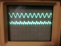
I'm trying to take a small differential signal (~10mV), amplify it, and then fullwave rectify it using only single supply opamp configurations. To do this I'm taking advantage of the differential amplifiers reference pin and giving it +Vs/2. This causes the output to have a DC offset wrt to GND (0V) [V1 below]. I then pass it through a HPF to remove this offset before sending it to the fullwave rectifier [V2 below]. See the attached image.
2014-09-01 15.05.44.jpg

I've got both phases working independently. The differential amplifier and the HPF output the correct waveform when not connected to the fullwave rectifier portion of the circuit [everything after V2] and the fullwave rectifier will take a waveform similar to V2 and output a wave form similar to Vout.

However, when I connect the output of the HPF to the input of the fullwave rectifier circuit, the signal at V2 gains a DC offset close but not exactly back to where it was at V1!

What can cause this?!

(The differential amplifier is AD8226 and the gen purpose opamp (rectifier phase) is a LM6134. Both opamps are using the same +Vs and GND planes.)

Thanks for your time,
Brian
 

kubeek

Joined Sep 20, 2005
5,794
I don't see how you expect to achieve full wave rectification. According to my books the circuit has gain of 1, and certainly no rectification is happening.
 

Thread Starter

NullPoint

Joined Jul 16, 2011
26
I don't see how you expect to achieve full wave rectification. According to my books the circuit has gain of 1, and certainly no rectification is happening.
Thanks for replying kubeek.

The rectifier phase is supposed to have a gain of 1. The differential amplifier does all the amplifying. As for how the rectifier works, check out this web article http://electronicdesign.com/archive/full-wave-active-rectifier-requires-no-diodes .

Also, I should have probably mentioned this in my OP but I'm not going on simulations or anything. I've got this circuit breadboarded up on my worktable. It does achieve fullwave rectification when I input a sine wave. It also is correctly rectifying the signal when both phases are connected but since the input signal has the problematic DC offset only the little nub of the wave form that drops below zero gets rectified not half the waveform as is anticipated.
 

MikeML

Joined Oct 2, 2009
5,444
66.jpg That edn circuit very much depends on the opamps being rail-to-rain In and Out. Are yours?

For it to work, the opamp's input common-mode range must include ground, and the opamp output pin must be capable of pulling within mV of ground.
 
Last edited:

Thread Starter

NullPoint

Joined Jul 16, 2011
26
View attachment 72525 That edn circuit very much depends on the opamps being rail-to-rain In and Out. Are yours?

For it to work, the opamp's input common-mode range must include ground, and the opamp output pin must be capable of pulling within mV of ground.
This is the opamp I'm using in the rectifier portion.
http://www.ti.com/product/lm6134

  • Rail-to-Rail Input CMVR −0.25V to 5.25V
  • Rail-to-Rail Output Swing 0.01V to 4.99V
 

crutschow

Joined Mar 14, 2008
34,285
The problem is that your full-wave rectifier has an unsymmetrical input impedance (which is common for many precision op amp circuits). It's very high for the positive half of the sinewave (the input looks like a follower) and 3.3k for the negative half. This acts as a rectifier to the capacitor output, causing a DC voltage and generating the offset you see. Just use one of the remaining op amps in the LM6134 package as a non-inverting buffer at the capacitor/resistor output.
 

Thread Starter

NullPoint

Joined Jul 16, 2011
26
The problem is that your full-wave rectifier has an unsymmetrical input impedance (which is common for many precision op amp circuits). It's very high for the positive half of the sinewave (the input looks like a follower) and 3.3k for the negative half. This acts as a rectifier to the capacitor output, causing a DC voltage and generating the offset you see. Just use one of the remaining op amps in the LM6134 package as a non-inverting buffer at the capacitor/resistor output.
You mean like this?


With the HPF output connected to the positive input?

If so, I tried that =/ It still introduced a DC offset. Do i need to tie the negative terminal to ground with a resistor?
 

crutschow

Joined Mar 14, 2008
34,285
You mean like this?


With the HPF output connected to the positive input?

If so, I tried that =/ It still introduced a DC offset. Do i need to tie the negative terminal to ground with a resistor?
Sorry, I forgot you are using a single supply so the amp input likely conducts on the negative excursion, still giving the observed offset. Let me mull on this a little further.
 
Last edited:

Thread Starter

NullPoint

Joined Jul 16, 2011
26
You mean like this?


With the HPF output connected to the positive input?

If so, I tried that =/ It still introduced a DC offset. Do i need to tie the negative terminal to ground with a resistor?
Just tired it again. I was wrong it does remove the DC offset but the buffer output is missing the negative portion of the waveform. Is there a limit i can amplify the signal in the initial phase to work with the rectifier? Seems like the buffer is snapping to the negative 0V rail.
 

crutschow

Joined Mar 14, 2008
34,285
Below is the sim of a precision rectifier that is offset by 1/2 the supply voltage to rectify a signal that is offset by the same amount. It does require diodes but it doesn't require a coupling capacitor. The 2.5V offset is then removed by the differential amp at the output.

I didn't have a model for your op amp so I used a similar rail-rail type.

Note that R8 is just a simulated load and is not required in the real circuit.

Precision Rectifier.gif
 

Thread Starter

NullPoint

Joined Jul 16, 2011
26
Below is the sim of a precision rectifier that is offset by 1/2 the supply voltage to rectify a signal that is offset by the same amount. It does require diodes but it doesn't require a coupling capacitor. The 2.5V offset is then removed by the differential amp at the output.

I didn't have a model for your op amp so I used a similar rail-rail type.

Note that R8 is just a simulated load and is not required in the real circuit.

View attachment 72530
Just tried your circuit. It does rectify the signal but is extremely noisy. Too noisy for my purposes =\
20140901_220657.jpg
 

crutschow

Joined Mar 14, 2008
34,285
That noise is not caused by the particular circuit design, it's cause by pickup or a noisy signal voltage. The circuit itself just has a gain of one so would introduce very little intrinsic noise on its own.

What is the amplitude of the signal in your scope photo? It appears to be rather small.

What power supply are you using? You might try adding a large capacitor (say 270uF) to ground at the input to the Vref amplifier (junction of R9 and R10) to ground in case power supply noise is getting into the Vref signal.

What is the highest signal frequency?
 
Last edited:

crutschow

Joined Mar 14, 2008
34,285
After doing some further simulation, the circuit may be oscillating. Try connecting a 100pF or so capacitor across R2. If that doesn't work I have an alternate circuit to try.
 
Last edited:

Thread Starter

NullPoint

Joined Jul 16, 2011
26
Below is the sim of a precision rectifier that is offset by 1/2 the supply voltage to rectify a signal that is offset by the same amount. It does require diodes but it doesn't require a coupling capacitor. The 2.5V offset is then removed by the differential amp at the output.

I didn't have a model for your op amp so I used a similar rail-rail type.

Note that R8 is just a simulated load and is not required in the real circuit.

View attachment 72530
That noise is not caused by the particular circuit design, it's cause by pickup or a noisy signal voltage. The circuit itself just has a gain of one so would introduce very little intrinsic noise on its own.

What is the amplitude of the signal in your scope photo? It appears to be rather small.

What power supply are you using? You might try adding a large capacitor (say 270uF) to ground at the input to the Vref amplifier (junction of R9 and R10) to ground in case power supply noise is getting into the Vref signal.

What is the highest signal frequency?
The input signal has an amplitude of 1V and 1kHz freq. I'm using a 9V battery as a power supply.

Since batteries are pretty noisy as power supplies, I just tried adding 1uF capacitors between +Vs and GND and Vref and GND (U3 output junction).

I also added a 1uF capacitor to ground at the R8 junction (it's the largest I have on hand). These two additions seemed to clean the signal up quite a bit but the shape of the output signal is still a bit wonky (pointed peaks of half the waveform).
new signal.jpg major x divisions are 1ms and major y divisions are 2V.

PS I also plan on smoothing the rectified signal with a low pass filter to get the envelope of the input waveform.
 

Attachments

crutschow

Joined Mar 14, 2008
34,285
The thickness of the waveform may still indicate an oscillation. Try increasing to sweep speed to 1us/div or faster to see if the fuzziness is actually an oscillation. Don't know why the rectified peaks are sharp, they should be rounded.

Also the uneven peak voltages of the rectified waveform indicates a difference in voltage between the 2.5V offset from the input differential amp and the 2.5V Vref going to the rectifier circuit. Are they the same voltage?

Below is the sim of a variation on the circuit that may be less prone to oscillation since its feedback loop only goes around one op amp, not two.

Precision Rectifier.gif
 

Thread Starter

NullPoint

Joined Jul 16, 2011
26
The thickness of the waveform may still indicate an oscillation. Try increasing to sweep speed to 1us/div or faster to see if the fuzziness is actually an oscillation. Don't know why the rectified peaks are sharp, they should be rounded.

Also the uneven peak voltages of the rectified waveform indicates a difference in voltage between the 2.5V offset from the input differential amp and the 2.5V Vref going to the rectifier circuit. Are they the same voltage?

Below is the sim of a variation on the circuit that may be less prone to oscillation since its feedback loop only goes around one op amp, not two.

View attachment 72557
I think the fuzziness is an artifact of the picture. The traces are actually pretty sharp.

Both input and Vref are using the same offset voltage source.

Does the new circuit reqyure 20kOhm resistors or will 10kOhm suffice?
 

crutschow

Joined Mar 14, 2008
34,285
Well, if it's not oscillating then changing the circuit won't affect whatever noise you are seeing.

You can use 10k ohm resistors in place of 20k as long as they are all the same.

You can adjust the offset between the two peaks of the rectified waveform by using a 20k pot (or 10k pot in series about 5k) in place of R2 to adjust the gain of the inverting half of the signal.
 

Thread Starter

NullPoint

Joined Jul 16, 2011
26
Well, if it's not oscillating then changing the circuit won't affect whatever noise you are seeing.

You can use 10k ohm resistors in place of 20k as long as they are all the same.

You can adjust the offset between the two peaks of the rectified waveform by using a 20k pot (or 10k pot in series about 5k) in place of R2 to adjust the gain of the inverting half of the signal.
Urghh so close! Unfortunately, the output signal from the AD8226 has a slight offset from Vref in my application. I tried to counter the offset by AC coupling the IA inputs (by adding HPFs to each) so they were centered wrt Vref. However, this led to a large 60Hz noise artifact manifesting in the output signal. :(

Would an AC coupling circuit like this one in the AD8236 spec sheet work with my original rectification circuit or would there still be an issue with it creating a DC offset upstream?
ad8236 AC coupling.PNG
 
Top