Op-Amp configuration will not stabilize

Thread Starter

Domophone

Joined Sep 10, 2013
65
Hi Guys,
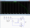
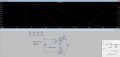
I've got a circuit in SPICE i cannot, for the life of me, make work how i intend. It is supposed to be a current source. It is currently set up with a dummy load (D)

So the general idea here is U2 acts as the current source. U3 is a transimpedance amp outputting a voltage = -R1*Iout(u2). U4 is a non inverting summing amplifier, which sums the output of the transimpedance amp with a setpoint (Vset+(-R1*Iout[u2])). This sum is then fed into the noninverting input of U2. U2 should then attempt to hold the non inverting input at GND (inverting input) by varying its output. This should close the feedback loop.

This is how it works in my head. But ltspice just shows oscillation (even when using ideal op amps). Can somebody point out what I've done wrong.

Thanks
 

Attachments

AlbertHall

Joined Jun 4, 2014
12,346
It works with LM308 so it is likely the frequency/phase relationship of the amps. Some bandwidth limiting is required.
What is R3 for?
 

Thread Starter

Domophone

Joined Sep 10, 2013
65
R3 along with
It works with LM308 so it is likely the frequency/phase relationship of the amps. Some bandwidth limiting is required.
What is R3 for?
Sorry, R3 is incorrectly placed. it should be coming off the inverting input of U3 to ground, setting the feedback for the summing amplifier. good catch
 

crutschow

Joined Mar 14, 2008
34,443
Your circuit has too many op amps in the loop, making it difficult to stabilize.
Generally more than one op amp in series with the feedback loop around both will be unstable or oscillate.

All you really need is one op amp.
Below is the simulation of the circuit with a common 741 opamp.
The direction of D1 had to be reversed due to the signal polarity change, but I wouldn't think that's a problem.

upload_2016-10-21_14-21-28.png
 

Attachments

Thread Starter

Domophone

Joined Sep 10, 2013
65
Hey,
Thanks for the solution. I was hoping to use two op amps, since i require a large current output (+/-200mA) but also need very low bias current for the trans-impedance conversion. Likely you know op amps are one or the other. In addition, I'd like to be able to add an alternate feedback loop to fix the voltage across the load, instead of the current, at a later time. I'd still like to be able to measure the output of the trans-impedance amp, when it is in voltage feedback mode though.

It's got me interested in stability analysis of a circuit with an op amp in the feedback loop.

I've done simpler stuff before, by following Linear Tech's videos, like:

But this circuit appears to be significantly different to me, and none of the plots i'm getting look close to normal for me.

How would i go about beginning stability analysis of the attached circuit. For example, to start, I'd like to plot the open loop gain of the system.

With a single op amp, IIRC, you should just be able break the feedback loop and add an AC stimulus, then take Vout/(Vnoninverting-Vinverting)

I get gibberish (or what looks like gibberish to me) if i try and do this with a two amp configuration
openloop_current2.jpg

Can somebody push me in the right direction? What are the criteria for stability in this case?
 

Attachments

crutschow

Joined Mar 14, 2008
34,443
That is a rather odd circuit.
Your need for a "trans-impedance conversion" does not make sense to me.

First off it oscillates at about 1 MHz (try the transient simulation with UIC, upload_2016-10-24_13-50-37.png) since you have two op amps in series with no local feedback which, as I previously noted, is just about guaranteed to oscillate.

Next, use at least 1000 points per decade in you AC analysis, not 1.
Below are some AC gain plots.
The high peak of Vout starting at about 100kHz is likely what's causing the oscillations.

upload_2016-10-24_13-49-2.png

upload_2016-10-24_13-56-35.png
 

Attachments

Last edited:

Thread Starter

Domophone

Joined Sep 10, 2013
65
Before i delve too far into attempting this odd circuit, maybe i'm putting the cart before the horse.

I made up my original (full) intended circuit in java circuit sim so you can tell me if it's a ridiculous method for achieving my overall goal. I like this sim as a first step, since it is very simple.

Link to simple simulation here: https://tinyurl.com/z2bqgrn

Here is an annotated image of the circuit:
Annotated.png

My intention is to be able to:
a) select to control either current or voltage for the load, and then set either one (my current range is ~+/-200mA, voltage range+/-3V)
b) measure the current & voltage going through the load at all times.
c) The current/voltage needs to be able to swing both negative and positive
d) The load should not have any common mode voltage

SPICE is my second step. I now know you cannot put more than a single op amp in the feedback loop in reality, so I've got some reworking and then some compensating to do.

As you can probably tell, it has been a while since I've done any type of stability analysis, and never before with an op amp in the feedback loop.

So am i re-inventing the wheel here? Is there a much easier way to achieve all my goals that I've overlooked?
 

Thread Starter

Domophone

Joined Sep 10, 2013
65
I compensated it with some local feedback on U2 (compensated1.jpg ), and it appears to be working in SPICE as intended. Still curious to get opinions on the larger circuit idea. High bandwidth isn't so important to me, a 50 kHz is sufficient.

AC Plot of compensated loop: compensated1.jpg
 

Attachments

Top