OP Amp circuit questions

Thread Starter

Milkgod

Joined Mar 9, 2017
21
Hello, I'd like to start off by saying that this is an assignment so I would appreciate anyone answering with advice or pointers to where I can learn and find the information.

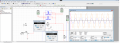
Attached is a screen cap of the op amp circuit. I'm interested in the negative feedback loop, specifically the diodes. To me it looks almost like it is a rectifier but I'm not sure if it's doing more in the circuit. I haven't be able to find similar circuits online detailing the point of the diodes. The assignment states " Explain the purpose of the diode network and how the formula for gain is affected"

Thanks
 

Attachments

Jony130

Joined Feb 17, 2009
5,487
Have you tried to remove these diodes form the circuit and see the simulation result?


Also, do you know that when the diode is conducting current it has some dynamic resistance?

And this rd resistance is now connected in parallel with R1 resistor. So the equivalent resistance has changed.
 

Thread Starter

Milkgod

Joined Mar 9, 2017
21
Have you tried to remove these diodes form the circuit and see the simulation result?


Also, do you know that when the diode is conducting current it has some dynamic resistance?

And this rd resistance is now connected in parallel with R1 resistor. So the equivalent resistance has changed.
with out the diodes there seems to be no amplification.
 

ebp

Joined Feb 8, 2018
2,332
One of the advantages of simulation is that if you want to connect 20 instruments to the same circuit at the same time you can do it very easily. Look at currents. Op amp circuits are all about where current goes as the amplifier maintains the voltage between its input pins at zero.
 

bertus

Joined Apr 5, 2008
22,270
Hello,

How is the supply voltage of the opamp arranged?
When you use a single powersupply, the output can not go below the 0 Volts.

Bertus
 

Jony130

Joined Feb 17, 2009
5,487
Try to use some "real opamp" (LM358) instead of this "virtual" one. Because this is not the way how a real-world circuit will behavior without these diodes.
This is why it will be hard to see for you what these diodes are doing in multisim.
Also try to google automatic gain control in wien bridge oscillator,
 

ebp

Joined Feb 8, 2018
2,332
OK, we know the circuit works with the diodes - that has been demonstrated in the original post. The power supply is fine, everything is connected properly.

The question is "what are the diodes in there for?"

Again I suggest looking at the currents through the diodes at the same time you are looking at the output of the amplifier, and think about what is going on and what current flow through the diodes means in terms of the instantaneous gain of the amplifier.

Consider carefully what is required for stable oscillation - there are two conditions that must be met in going "around the loop."
 

Thread Starter

Milkgod

Joined Mar 9, 2017
21
OK, we know the circuit works with the diodes - that has been demonstrated in the original post. The power supply is fine, everything is connected properly.

The question is "what are the diodes in there for?"

Again I suggest looking at the currents through the diodes at the same time you are looking at the output of the amplifier, and think about what is going on and what current flow through the diodes means in terms of the instantaneous gain of the amplifier.

Consider carefully what is required for stable oscillation - there are two conditions that must be met in going "around the loop."
Current on both diodes is 37.3 kA (seems like a lot to me). The resistance fluctuates from 1 Kohm to about 7 Kohm. Are the diodes controlling the gain?
 

Attachments

bertus

Joined Apr 5, 2008
22,270
Hello,

A current is measured in series with a component and not accross a component.
A voltage can be measured accross a component.

Bertus
 

ebp

Joined Feb 8, 2018
2,332
"Current on both diodes is 37.3 kA (seems like a lot to me)."

A lot - yes. Yes it is.
You have put a current meter across something when you want to measure the current through it.

What you really want to do is look at the waveform of the current so you can see when current is flowing relative to the output waveform of the amplifier.
 

ebp

Joined Feb 8, 2018
2,332
If you can't directly use an oscilloscope function to measure current, remember Mr. Ohm. Put a small resistor in series and measure the voltage across the resistor.
 

Thread Starter

Milkgod

Joined Mar 9, 2017
21
"Current on both diodes is 37.3 kA (seems like a lot to me)."

A lot - yes. Yes it is.
You have put a current meter across something when you want to measure the current through it.

What you really want to do is look at the waveform of the current so you can see when current is flowing relative to the output waveform of the amplifier.
I tried wiring up the multi meters properly. One other thing is when I flip the way it is wired the reading is back at kA range. I'm guessing the uA is the correct reading.
 

Attachments

WBahn

Joined Mar 31, 2012
29,979
Current on both diodes is 37.3 kA (seems like a lot to me). The resistance fluctuates from 1 Kohm to about 7 Kohm. Are the diodes controlling the gain?
That's because you are not measuring the currents in the diodes. You are measuring the current through a circular short circuit created by the two meters and the current is then indeterminate. The simulator settles for the first value that satisfies it's constraints and it happened to come out to be a few dozen kA.

To measure a current you need the meter to be in SERIES with the component you are measuring, not in parallel.
 

ebp

Joined Feb 8, 2018
2,332
Again - we are interested in the waveforms of the currents through the diodes, not the DC values. You must use oscilloscopes, not meters. There should be a way to directly display the current in a connection. If there isn't then you must add current sense resistors (e.g. 1 ohm for convenience - the voltage drop across 1 ohm due to the currents actually expected will be negligible).
 
Top