 Facebook
 Google
 GitHub
 Linkedin
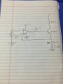
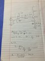
Op amp circuit design
- Thread starter Lewa129
- Start date
| Thread starter | Similar threads | Forum | Replies | Date |
|---|---|---|---|---|
|
|
Logic D | Homework Help | 53 | |
| S | Circuit design for battery backup | General Electronics Chat | 10 | |
|
|
Pre-Amp Circuit Design For Piezo-Electric Disk | Analog & Mixed-Signal Design | 17 | |
| T | analog IC design in the submicron technology (12nm<L<180nm) | IC Design | 0 | |
| V | IR2111 Circuit design for Half bridge control ..#2 | General Electronics Chat | 3 |


