Op Amp choice for buffering Audio Signals generated with Arduino

Thread Starter

Hamalz

Joined Oct 14, 2018
13
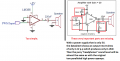
Hi everyone, I'm currently working on the implementation of an Audio Synthesizer based on Arduino Micro. I managed to generate different waveforms using fast PWM and filtering the signal. The output signal ranges from 0V to 5V and I brought it down to 2V using a voltage divider, in order to obtain 1Vpp after AC coupling with a capacitor, which should be close enough to line level. The problem I'm encountering right now is that the output signal is strongly distorted by the load (e. g. a small speaker), so I found this article stating that I need to use an Op Amp as a buffer. The device used in the article seems to be discontinued, and I don't feel comfortable to go for the first device I found online: so here I am, asking if anyone of you knows what device could be the best for this use, since I'm quite overwhelmed with the number of available op amps in the industry and this is my firs project ever. In particular, I'm not quite sure how to choose the device GBWP and slew rate suitable for not-so-complex Audio Signals. I'm quite sure I will need a Single Supply Op Amp since it will be powered off Arduino's 5V supply... Maybe a TLC081 is ok?
Thanks for your help!
 

MrChips

Joined Oct 2, 2009
30,823
Welcome to AAC!

You need two simple steps before you can connect to a loudspeaker.

1. Low pass filter to convert PWM to analog.
2. Loudspeaker amplifier.

What are you using for the loudspeaker amplifier?
 

Thread Starter

Hamalz

Joined Oct 14, 2018
13
Hi!
I'm filtering the signal with a simple RC low pass filter and the waveforms look pretty good, however I'm not using any amplifier yet: I thought it wouldn't be necessary for now (turns out I was wrong, I guess!), since the project is still developing and a small 0.5W 8ohm speaker is all I need to monitor the output, although this is a temporary situation... My aim is to obtain a device that I can connect to any external speaker/amplifier as I do with a smartphone or mp3 player.
 

crutschow

Joined Mar 14, 2008
34,464
You need an audio amplifier that can drive the low impedance loudspeaker load.
A standard opamp won't work, as the minimum resistance they can drive is usually a kΩ or so.
You can buy or build such as amp.
Here are some built examples.
 

Thread Starter

Hamalz

Joined Oct 14, 2018
13
Thank you for you reply.
So this means that every device with audio output such as a smarphone/pc/ipod jack has an amp in it?
Since I'm looking to connect my Synth to external amplifiers/amplified speakers I don't think I will need a lot of power... I guess I will have to choose an amp delivering the same power as an ipod, is there any standard power level I should look for?

This is what the article I read says about amplification with a simple op amp:
Many times when we talk about amplifiers we think about circuits which increase the amplitude of a signal. In this case I'm talking about increasing the current of the signal so that it can drive a load (like a speaker). In this stage of the circuit I set up both op amps on one TS922 package as parallel voltage followers. What this means is I sent the output from the amplitude pot to the non-inverting input of both op amps. Then I wired both op amps as voltage followers and connected their outputs to each other. Since each op amp can source 80mA of current, combined they can source 160mA of current.
 
The OP amp in the article is not a bad part. It's just that the DIP package is going the way of the dinosaur.

Adapters such as these: https://www.proto-advantage.com/store/advanced_search_result.php?keywords=TSSOP-8

are used to breadboard with SMT components. PA can actually procure and mount a digi-key p/n on the adapter.

Some possibilities are: https://www.digikey.com/products/en...000&quantity=&ColumnSort=0&page=1&pageSize=25

Differences are mostly offset voltage and automotive qualified.

The adapters can be made with machined DIP pins or square pins. The square pins are good for solderless breadboards.

The adapters can usually be procured at Digikey and other places,but PA offers a value added service.

SMT components are usually mounted using a solder paste through a mask and then heated with say a toaster oven, hot air gun or even a soldering iron. Solder paste has a limited life. I like the paste containing a small amount of Bismith.

"small speaker" does require some clarification. The buffer is always good. A power amplifier is usually used to drive a "real speaker". That may require a higher output voltage and current and operate on a power supply larger than 5V.

1 V p-p is basically what's called consumer line levels. The ability to drive 600 ohms places it in a better category. Commercial stuff will use XLR connectors and a differential output.

You might find an LM383 or LM1875 based amplifier on ebay or aliexpress.
 

Audioguru

Joined Dec 20, 2007
11,248
Simply calculate how much output power the peak current of 160mA from two paralleled high current opamps produce into an 8 ohm speaker.
160mA squared x 8= 0.2W and the real RMS output power is only 0.1W like loud headphones.

A PAM8403 stereo (2 channels) power amplifier IC produces 2.5W per channel into 4 ohm speakers with low distortion with a 5V supply.
 

Audioguru

Joined Dec 20, 2007
11,248
Now he says his synth will feed an amplifier or an amplified speaker, so I do not know why he overloaded it with an ordinary speaker.
The LM386 amplifier schematic is missing important parts and produces an output level into a speaker that will sound the same as the puny level form the original two paralleled opamps:
 

Attachments

Thread Starter

Hamalz

Joined Oct 14, 2018
13
Thanks everyone.
I do not know why he overloaded it with an ordinary speaker.
This was a newbie's mistake. The only purpose of the speaker is to temporarily monitor the output until the complete output interface will be complete. I was confused by this article, stating:
The output pins can even drive a small (4cm or less) 8-ohm speaker connected directly between the pin and ground without any amplification.
My objective is still to feed an amplifier or an amplified speaker.
It's just that the DIP package is going the way of the dinosaur.
I didn't even imagine that the problem was the package... Being a homemade project of course I was looking for something I could solder on a perfboard, thanks for letting me know about those adapters!

Well, since driving a speaker is not what I aim for, I'll just use an oscilloscope to monitor the output for now... I guess the "problem" now is to obtain a signal with the same characteristics of a consumer line level signal from the current signal, which is 0 to 5V, with Arduino being able to output up to 20 mA (10 mA recommended) per pin... Does anyone know what I need to do? I'll do some research in the meantime
 

MrChips

Joined Oct 2, 2009
30,823
A simple solution is to find an external PC speaker with built-in amplifier, either battery powered or powered from a wall adapter. You can get these for a very low price at second hand stores.
 
It kinda depends on what you want.

1. You can bias the input +2.5 V or 1/2 Vcc
2. Use a rail splitter IC. This generates a low Z common at 1/2 the supply voltage.

If you can couple with a capacitor all the better.
 
Note on SMT soldering. The TSSOP-8 package isn't too bad to solder yourself on a "breakout board". That't the term used for those adapters for just about anything. USB, RJ45's, DIPs etc.

If you can use solder containing lead, 63/37 is a Eutectic mix, so the solidus and liquidus temperatures are the same which means it melts and solidifies instantly.

Generally you tack one corner and place the IC. Tack the other. Then drag the tip of the soldering iron over the pins. Solder bridges will remove themselves when the amount of solder is low enough. You do need a small tip.
This would be wire solder and a very small tip.

Lead free solder melts at a much higher temperature and it' difficult to work with.

It would happen that my very first SMT replacement was a processor chip in a car radio. Something like 40 pins 0.5 mm pitch diameter. I asked around and I used the cut the pins method for removal. Tack the corners and drag. It was suggested that I solder with the chip and pins facing downward. It worked well.

I have a habit of doing seeming "impossible tasks" since I was 6 years old. I wanted to paint three paint by numbers set of 3 Japanese women that were nearly 1.5' wide by 3' tall. They turned out well.
 

Thread Starter

Hamalz

Joined Oct 14, 2018
13
I just realized I previously quoted the wrong part of the article, that's probably why my request wasn't so clear at the beginning of this thread. This is the part in which the author talks about buffering the signal:
Now that we have a good signal coming out Arduino, we need to protect it. The R2R DAC is very sensitive to any loads put on it, so trying to drive speakers directly from the DAC will distort the signal heavily. Before doing anything with the signal you need to set up some kind of buffer circuit. I set up one of the op amps in the TS922 dual op amp package as a voltage follower to buffer my DAC from the rest of my circuit
This means that the author buffered the signal first, and then amplified it with another TS922... However she wants to drive a speaker, while I don't, so from what I understand I don't need to amplify the signal, I just need the voltage follower.

If you can couple with a capacitor all the better.
Do you mean coupling with a cap in addition or in place of biasing/using a rail splitter?
I've never done 1. or 2. before but from what I understand those procedures shouldn't be necessary if I use a single source opamp... Am I correct or am I missing something?

This is the procedure I came up with:
1. Use a voltage divider to reduce the signal's amplitude
2. Buffer the signal with a single source opamp (still not sure if it's necessary)
3. Attach a coupling capacitor in series with the output to get rid of the DC component
4. If I don't find any device with characteristics similar to the TS922 I'll put your advice on dealing with different packages/power supplies to good use.

I hope it doesn't look like I'm not listening to you at all and I want to keep doing things my way: it's not like that, it's just that I'm a bit confused by all the alternative solutions. It's now clear to me that as it is now, my device cannot drive an ordinary speaker, so I'll get my hands on some cheap amplified pc speakers to monitor the audio. Some of the circuit designs you sent me are suitable for driving small speakers so maybe they're too powerful for what I want to do. If you think the procedure I came up with is not correct, please let me know!
 

Audioguru

Joined Dec 20, 2007
11,248
Any half-decent audio amplifier of amplified speaker has a high input resistance that does not need a buffer, especially not a high current buffer like the TS922. All you need is a coupling capacitor to block the DC from the lowpass filter output of the R2R/DAC from messing up the volume control on the input of the audio amplifier or amplified speaker. Most volume controls are 20k ohms so to pass audio frequencies down to 40Hz the value of the coupling capacitor will be 0.16 divided by (20k x 40Hz)= 0.2uF, use a non-polarized 220nF or 330nF film capacitor.
 
Just a note:

Audio signals don't have any DC offset. If you have a 0-5 V supply and a bi-polar input, you have to bias the op-amp so it can amplify the bipolar signal. 1/2 the supply voltage is typical.

You can also use a bi-polar supply.

Single supply op-amps don;t quite amplify 0V (0V in = 0V out) and don't quite reach the supply voltage.

Most Op-amps can't see a signal greater than the rail voltage unless it's current limited. This can happen if the device is unpowered.
 

MrChips

Joined Oct 2, 2009
30,823
If you think the procedure I came up with is not correct, please let me know!
All of the above are correct.

1) Get a PC speaker amplifier. Amplifiers are already AC coupled going in.
2) As KISS says, audio does not have DC. You don't need a decoupling capacitor.
3) As AG says, amplifier inputs are high input impedance. You don't need a buffer.
 
All of the above are correct.

1) Get a PC speaker amplifier. Amplifiers are already AC coupled going in.
2) As KISS says, audio does not have DC. You don't need a decoupling capacitor.
3) As AG says, amplifier inputs are high input impedance. You don't need a buffer.
Generally you always need decoupling capacitors. These are small capacitors on the order of 0.1 uF and typically ceramic that are used as close to the power supply pins of nearly every IC. The manufacturer usually has recommendations. e.g. Voltage regulators may oscillate without them.

A coupling capacitor is different , This application isolates DC. A class A audio amplifier uses a large coupling capacitor to remove DC from reaching the speaker. The formula f=1/(2*π*RC) plays a major role in these applications. This is the -3 db frequency or when the output is down by √2. or aproximately 70.7%.
This is also the quoted bandwidth.

For a first order approximation, you can think of the capacitor as a short above f.

The oscilloscope has an input selector of GND, AC and DC which is somewhat "wrong". GND, AC and AC+DC would be a much better description or AC in this case really means time varying signals.

There are TRMS (True RMS) meters that will have AC and AC+DC options.
 
Top