Op Amp as voltage amplifier - 0..50mV to 0..5V

Thread Starter

flotul

Joined Aug 3, 2016
14
Hi there,

I'm using the first time an oxygen sensor (Oxiplus A OOA101). It's output is linear in millivolts, typically between 7 and 13 mV by common air (21/79).

To be able to use it with a µC, I need to amplify its signal by a factor of 100 (0..50mV > 0..5V).

Since I'm not used to with Op Amps, I designed the circuit with FALSTAD (https://www.falstad.com/circuit/) simulator and it looks okay here (I attached the circuit file to the post):
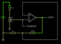
O2 Sensor Voltage Amplifier Non-Inverting.png


But when I build this circuit, I get no voltage on the output.

The pot is 100Ohms.

I tested the circuit with some op amps I have in the drawer (LM393N, MCP6291, LM358N) but non will give me a "positive" result.

What am I missing...

Thanks for any help ;-)

Roger
 

Attachments

dl324

Joined Mar 30, 2015
18,447
What am I missing...
You didn't give us a power supply voltage, but I calculated it to be 5V. LM358 output voltage isn't guaranteed to work for your application. LM339 is an open collector comparator, not an opamp. Did you have a pull-up resistor? Don't know what MCP6291 specs are without looking them up.

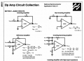
Your circuit would be easier to read if you drew it more conventionally. There are many examples in available literature:
1694274249990.png
 

Ian0

Joined Aug 7, 2020
13,227
You have the inputs swapped.
For a gain of 100, you will need a good op-amp if you want it to be accurate (low offset voltage, low bias current),
I would use a MCP60x1 (there are several versions with different numbers for x depending on how fast it needs to be).
By the way, your circuit (when you have the inputs the right way round) will have a gain of 101 not 100, but you are unlikely to get closer unless you use E96-series resistors.
 

crutschow

Joined Mar 14, 2008
38,674
A lesson here. This shows how flaky the Falstad simulator is, giving a normal looking output for the shown incorrect circuit configuration with positive feedback.
Best to go with a Spice-based simulator such a P-Spice, Tina, or LTspice as they are unlikely to make such an error.

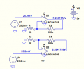
Below is the LTspice sim showing the incorrect and correct circuit configuration:
The output for the top configuration with positive feedback goes to the negative rail (near ground) as would be expected, whereas the bottom circuit with negative feedback gives the correct result.

Note that the input offset voltage of the LM358 in a real circuit can be too high to give an accurate output voltage.
You will need a low offset op amp, such as the one suggested by Ian0.
Minimum offset would be achieved by an auto-zero type op amp, which you may need for the best accuracy.
1694278065920.png
 
Last edited:

Thread Starter

flotul

Joined Aug 3, 2016
14
Thanks all for your messages.

Yes, power supply is 5 Volts.

I rewired the MCP6291 I have like in crutshow's second example and it works fine now.

I'll also give a try to other simulators.....

Thanks again to all ;-)
 

Ian0

Joined Aug 7, 2020
13,227
Thanks all for your messages.

Yes, power supply is 5 Volts.

I rewired the MCP6291 I have like in crutshow's second example and it works fine now.

I'll also give a try to other simulators.....

Thanks again to all ;-)
MCP6291 has a maximum offset of 3mV. That will give a maximum error of 300mV after amplification, so perhaps you might need a better op-amp.
What would happen to your system if the input voltage were 300mV higher or lower than it really should be?
 

crutschow

Joined Mar 14, 2008
38,674
By adding a couple extra components, it is possible to trim out any offset Voltage effect at the OPA output
That will certainly work, but it might be simpler just to use an auto-zero op amp, which can have well less than a mV offset, and also maintains that for any drift due to temperature.
 

ericgibbs

Joined Jan 29, 2010
21,531
Hi Carl,
I agree, if the TS can use an auto zero amp, but suggesting alternative solutions is always a good idea.
It may also make other budding engineering types aware of the options.
E
 

Ian0

Joined Aug 7, 2020
13,227
The MCP6071 gets the offset down to ±150uV without the expense of an auto-zero amp or the necessity to trim each one with a preset. To make a one-off the additional time for calibration is hardly a consideration but for a batch of fifty it is beginning to cost significant amounts of labour time.
 

Thread Starter

flotul

Joined Aug 3, 2016
14
I highly appreciate all your comments but...I'm just a modest rookie in electronic science.

If I choose to go with a MCP6V11, will I be on the good side of the "force" or is there any other and better choice I should go for?

2023-09-10 22_22_56-AMPLI-OP_MCP6V11_zero-drift.pdf - [MCP6V11_1U_2_4 Data Sheet] - SumatraPDF.png


I don't have to look at any cost consideration since this is going to be a small production for a few diver friends and myself - maybe 20 circuits.

My actual MCP6291 seems to work well but it isn't a "zero-drift" or "auto-zero" (is it identical?) op amp...

BTW, what are these last op amp types really do, being something "zero"?
 

Ian0

Joined Aug 7, 2020
13,227
My actual MCP6291 seems to work well but it isn't a "zero-drift" or "auto-zero" op amp...
But what about the other 19? The offset voltage is random. If you got lucky and your first MCP6291 had zero offset, would your friends suffocate if the second one had the maximum 3mV offset? How much difference in oxygen concentration does 3mV represent?
 

Thread Starter

flotul

Joined Aug 3, 2016
14
Yes, it has to be quite precise indeed.

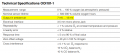
The sensor's data sheet specifies a range between 7 and 13mV in air (21/79) and the scale is "linear".

2023-09-10 22_37_10-Clipboard.png

Since 21% of O2 is ~10mV, I assume that 20mV equals 42% and so forth.

This sensor looks to be one of the most used in oxygen analyzers so I think this a good one to start with.
 

crutschow

Joined Mar 14, 2008
38,674
Here is a listing from Digikey for some inexpensive, zero-drift (auto-zero) op amps that you may want to consider.

The MCP6071 low offset op amp that Ian0 suggested should also work.
 

Ian0

Joined Aug 7, 2020
13,227
Yes, it has to be quite precise indeed.

The sensor's data sheet specifies a range between 7 and 13mV in air (21/79) and the scale is "linear".

View attachment 302510

Since 21% of O2 is ~10mV, I assume that 20mV equals 42% and so forth.

This sensor looks to be one of the most used in oxygen analyzers so I think this a good one to start with.
I’m dubious of the 7mV to 13mV spec. I’d like to see a graph of p(O2) vs. Voltage, showing error limits, before I would Design anything that might be classed as “medical”.
 

Ian0

Joined Aug 7, 2020
13,227
So you think the data sheet is in error?
I don't think an air oxygen sensor it classified as "medical".
1)That line has a certain vagueness to it, that makes me suspicious. I have looked at the datasheet and I can't really figure out how the output voltage relates to the oxygen concentration. There's a figure of 40uV in 100% nitrogen which I suppose refers to the output in 0% oxygen, but no figure for the output in 100% oxygen.
2) The TS mentions "for a few diver friends", which seems to put the project in the "life support" category which most semiconductor manufacturers preclude from their warranties.
 
Top