Thinking more I think I can nudge this along whether it is or isn't homework. Try using KVL/KCL to see what the difference is. In other words, what are the voltages and currents through all the nodes/components?
Thinking more I think I can nudge this along whether it is or isn't homework. Try using KVL/KCL to see what the difference is. In other words, what are the voltages and currents through all the nodes/components?
Please use a thread title pertaining to the topic.
A title such is "General" is meaningless and is of no use to any one.
Here is a suggested title "one or multiple series resistor for LEDs"
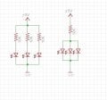
Assuming you have the correct voltages and resistances - the one on the left has the potential to work whereas the one on the right has the potential for catastrophic failure.
Please use a thread title pertaining to the topic.
I title such is "General" is meaningless and is of no use to any one.
Here is a suggested title "one or multiple series resistor for LEDs"
hi shibin,
The right side circuit will work OK providing the LED forward voltages are matched ie: the same voltage.
They will share the 10k current equally , so be dimmer.
The left side circuit will work with any LED forward voltage, they do not need to matched for forward voltage.
E
Assuming you have the correct voltages and resistances - the one on the left has the potential to work whereas the one on the right has the potential for catastrophic failure.
Never mind the voltage and resistance. The current through each LED is same in both the cases. and the voltage (I think). Then how will the second will be a failure.
Just so you know, the circuit on the right has the potential for catastrophic failure. First, your voltages and resistances are wrong. I won't focus on how or why. However, the reason why the one on the right is in danger of complete failure is because one of the diodes will hog the current. Meaning if you pump too much current through the circuit you will blow that hogging diode. Then the next diode will then hog the available current and blow. Finally the last one will blow. And it will happen VERY fast. You would likely not have sufficient time to shut down the circuit.
Do you know how to calculate the correct resistor for the LED (just one of the three) on the left? An understanding of how they are calculated will reveal why I said the one on the left has the potential to work. At present, the way you designed it - it won't work. It won't fail but it will fail to work. What's the difference? Failure of the right side means the components are ruined. Whereas failure to work means it just won't do what you hope it will. The components themselves will be unharmed. Like trying to light a household lightbulb using a 9 volt battery.
hi shibin,
The right side circuit will work OK providing the LED forward voltages are matched ie: the same voltage.
They will share the 10k current equally, so be dimmer.
The left side circuit will work with any LED forward voltage, they do not need to matched for forward voltage.
E
Say each led need 30mA to glow. So the source will provide 90mA total current. And the same 5V there across each led-resistor pair.
Similarly, in the second case, The source will provide 90mA of current. and 5V across led-resistor pair(I think).
For 30 mA at 5 V you'd need a resistor value of (and I'm assuming a forward voltage for the LED at 2V) would be a 100Ω resistor. 10KΩ is just way too high. At that resistance your LED will only see 0.3 mA (0.0003 A). IF your LED lights up - you'd probably need a match just to see if it's glowing.
[edit] BY THE WAY - - - 30 mA is a LOT of current for a typical LED. Unless you're talking about one of those LED's that are used as a light source. But then in that case 30 mA is rather small. Especially given the use of 5 volts.
I'm working from the notion of "Which is correct". As I said, resistances and voltage not withstanding (because as posted it's obvious an LED can not work on 300 µA (micro-amps, not milli-amps)).
Just to be clear, the sort of LED I'm assuming we're discussing is this type:
Depending on color - so the forward voltage will change. Different colors have different forward voltages. ASSUMING we have a typical RED LED, typically 2 Vf (forward voltage) at 10KΩ there's not enough for ANY of the above circuits to either work OR fail. That's why I said voltage and resistances not withstanding - the principal is that the circuit on the right would (unless all three LED's were identically matched for Vf and would draw identical current, which isn't easy to do) the circuit on the right has the potential for catastrophic failure. ASSUMING we use a reasonable voltage and resistance to even operate the circuit.
As @ericgibbs said, IF the Vf's are matched there's a chance the right circuit would work. But at diminished brightness. Again, on the assumption of proper voltages and resistances.
Tony has it right, the TS needs to figure out how to light a single LED from that +5V power source. Only then can they scale it to the 3x circuit and THEN determine why the right circuit could potentially be bad with a current hogging LED (or when an LED fails short).
If this IS homework - which I understood you to say it's not - don't give up. It may seem like a difficult concept to grasp, but in reality it's quite easy once you understand it. @ericgibbs has reposted your diagram showing how what you drew breaks out. 0.3 mA (300 µA) is way too low to light the LED's. ANY of the LED's. Let alone divide that 300 µA by three LED's, leaving just 100 µA per LED in the view on the right.
POTENTIALLY, assuming all three LED's are matched, with a 100Ω resistor (not 10KΩ) 30 mA divided between three LED's would give each an average of 10 mA. Which is optimal for LED's of this sort. Typical operation of an LED should range between 5 mA and 20 mA. 20 being the max I would ever operate an LED on. Any higher and the LED runs way too hot and seriously shortens its lifespan. 30 mA and it's cooking. May light for a few seconds, may even light for close to a half minute. But after that it would likely begin to degrade and diminish in brightness - until total failure. Trust me, I've sent plenty of LED's to the grave.
 Facebook
 Google
 GitHub
 Linkedin
 55.4 KB Views: 43


