I am not at all convinced the transformer is bad. I would try connecting it to mains and read the voltage on the secondary (orange) at this point before replacing it.
I am not at all convinced the transformer is bad. I would try connecting it to mains and read the voltage on the secondary (orange) at this point before replacing it.
It is set for 240V when the white wire is on the '0' terminal and the blue wire is on the '240' terminal (as it has been for the photos on here).
On the meter, look towards the top right of the switch. You will see 'V~' in orange. Directly under that is '200'. Set the switch to point to that '200'. That is the 200V AC setting (the '~' means AC). Then you are set for measuring the voltage on the orange wires. If the transformer is good you should see 7V (it might be a little higher than that if it is not plugged in).
If the transformer does need replacing then this one may be a better choice as it is toroidal so a few extra turns could easily be added to get the extra volt. (I would guess at about 5 or 6 extra turns.) Even though the SI-3032V regulator is a low dropout device the input voltage may still be a little low with 6 volts RMS into the bridge rectifier. (I have uploaded the datasheet for the regulator.
If the transformer does need replacing then this one may be a better choice as it is toroidal so a few extra turns could easily be added to get the extra volt. (I would guess at about 5 or 6 extra turns.) Even though the SI-3032V regulator is a low dropout device the input voltage may still be a little low with 6 volts RMS into the bridge rectifier. (I have uploaded the datasheet for the regulator.
So would I simply solder the blue and white transformer wires to one end and the orange to the other with this?
As I understand its only 6v output not 7v.
Thanks - so that means it's gone if the orange output shows = 0?
out of interest, why would it show 245 when I connect '0' to the 100/110 contacts?
Can I assume the blue and white cables are power coming in?
but it goes through the circuit board first before it enters the transformer, via a 250v fuse etc
I just don't get the flow and how it works.
I would have assumed that power went in to the transformer first before even touching the device circuit board. But again Im a total novice so open to basic lessons in how things work!
If the transformer was working correctly then you should read 100V between the '0' and '100'. That it reads 245V is further confirmation that the transformer is dead.
Can I assume the blue and white cables are power coming in?
but it goes through the circuit board first before it enters the transformer, via a 250v fuse etc
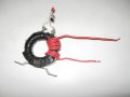
The fist thing to do is to establish how many turns per volt the transformer is. Wind on ten turns of insulated wire. (Just normal connecting wire will do.) Something like they way I wound some turns on this current transformer.
Insulate the ends of the red, black, yellow and orange wires from the transformer with insulating tape so they can't touch each other or anything else. Join the violet and grey wires from the transformer and insulate the joint. Connect the blue wire from the transformer to connector CN2 pin 1 (Was white wire from original transformer.) Connect the brown wire from the transformer to connector CN2 pin 1 (Was blue wire from original transformer.) Make sure the ends of your extra winding are not touching each other or anything else. Plug in the unit and switch it on. With your meter set to the 20 volts AC range measure the voltage between the ends of your winding. (TAKE CARE NOT TO TOUCH ANY OF THE WIRING.) Remove the power to the unit. The reading you get on your meter will be 10 times the voltage for one turn. You now need to calculate how many turns that you actually need. So for example if the reading is 1.5 volts then you will need 10/1.5 turns (= 6.6 so you would make your winding 7 turns.)
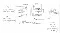
When you make you new winding wind it neatly so now turns will be squashed together by the mounting hardware. Try to use wire that will stand some heat as the transformer may run quite warm. Join the red and yellow wires from the transformer. Join the black and orange wires from the transformer and connect one end of your winding (We will call it A) to it. Re apply power. measure the voltage between the other end of your winding (We will call it B.) and the junction of the red and yellow wires. You will get a reading of about 7 volts or 5 volts. If it is 7 volts then your winding is connected correctly. If it is 5 volts you need to swap the end of your winding that is connected to orange and black wires. Insulate the junction of one end of your winding and the orange and black wires. Connect the transformer as shown in this diagram.
You will probably need to use a slow blow fuse for the primary larger than the 200 mA one shown on the schematic as toroidal transformers can have quite a high magnetising current. Also show us EXACTLY how you have mounted the transformer before powering on so we can check that you have not caused a shorted turn with any metal brackets you have made to mount the transformer.
Using an external 9 volt power supply connected to connector CN3 is probably the nearest thing to plug and play that would solve your problem. You would need to mount 1 2.1m coaxial DC inputs socket and connect it to connector CN3. as you would be feeding it through the bridge rectifier that would drop the 9 volts to about 7.7 volts which would be a suitable input voltage for the regulator. If you were prepared to remove the regulator using an external 5 volt DC supply would be a better solution. The output from this would be connected to the connection that was the original regulator output. Both of these solutions may cause problems due to noise on the mains supply and noise from the external switch mode power supply as you would be bypassing the mains input filtering on your unit. This is one possible 9 volt power supply on ebay.
Im still confused as to what to do to replace this transformer.
Should I get the 6v Transformer as recommended, as it seems easy to just pop it in and solder the inputs (Blue/White) and outputs (orange),
what issues might I face?
Of course the idea of getting a DC adapter (external), and soldering a DC input to the unit somewhere on the unit sounds good.
But 1. What exactly do I but, 2. where do I solder the input DC to on my device?

 Facebook
 Google
 GitHub
 Linkedin