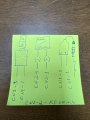
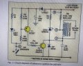
As I thought, your circuit is wrong. Here is my recreation of it in an easier to read form and its obvious why it fails. When you trigger the SCR all it is doing is shorting the supply. Once the SCR triggers there's nothing to turn it off until the output of the 350v supply drops below approx 10mA or it destroys itself...
The lower version limits the current with a 500 - 1kohm resistor. It works, but the resistor dissipates nearly 100W! So not practical...
The difficulty is the 350v supply. Current limiting its input works for now, but its still being stressed and reliability is suspect. Current limiting its output is not practical. Turning its output off by controlling its input is not likely to be practical due to its likely start-up time. Therefore two options remain (tho' open to other suggestions): (a) control its output with a 'switch' or (b) replace it with an alternate supply with more useful output characteristics. I'm currently (excuse pun) looking at option (a) tho' switching 350v on & off isn't easy.
What battery volts are available? 12v, negative ground?
And they all have the same issue - they are magneto powered so chopped DC input which turns itself off. except #2 which is not CDI just a transistor switch.
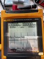
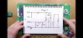
So I’ve been thinking about this and my trigger voltage generated by the coil in the magnet is of a sufficient magnitude to trigger my gate on my SCR. And my triggering waveform is sinusoidal (see picture). Doesn’t the negative part of this wave shut off my SCR?
 Facebook
 Google
 GitHub
 Linkedin