Oil well ignition module

Irving

Joined Jan 30, 2016
5,124
So I’ve been thinking about this and my trigger voltage generated by the coil in the magnet is of a sufficient magnitude to trigger my gate on my SCR. And my triggering waveform is sinusoidal (see picture). Doesn’t the negative part of this wave shut off my SCR?
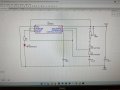
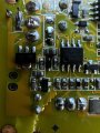
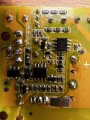
Once an SCR is triggered it stays on until the current through it drops below the holding current, typically 10 - 30mA. AFAIK there's no way to turn it off from the gate.
 

Thread Starter

MarkySparky42

Joined Aug 28, 2022
204
It has a DC input, but the TIP32 and associated transformer constitute an oscillator which supplies alternating current via the 104/400V cap to D3 for rectification to high voltage DC.
So what do you guys think? Should I go to AutoZone and get a $10 700 W inverter and just plug my little transformer in to make it work or is there a more eloquent solution?

going back to the very first response, I am now thinking that it makes more sense to make a better more “tuned“ power supply for this particular application. This engine running is the only source of income I have for my father‘s retirement and he doesn’t have extra $500 laying around all the time for when one of these ignition module decides to die.

I maybe I should go out and find a 555 timer circuit.

It sounds like a CDI module requires some sort of AC component but making a whole inverter seems overkill.
Sorry if I’m obsessing about this, but I really need guidance. To quote a famous princess “help me Obi Wan Kenobi, you’re my only hope”.
 
Last edited:

Alec_t

Joined Sep 17, 2013
15,119
It sounds like a CDI module requires some sort of AC component but making a whole inverter seems overkill.
As you already have a high voltage generator (unless you've killed it), I think a modified cap charge/discharge arrangement plus the ignition coil, should work, hopefully mainly using components you have to hand.
Although you had a system working ok from your 12V transformer, repetitive over-loading of that each time you charge the cap is not a good idea.
 

Thread Starter

MarkySparky42

Joined Aug 28, 2022
204
So what do you guys think? Should I go to AutoZone and get a $10 700 W inverter and just plug my little transformer in to make it work or is there a more eloquent solution?

going back to the very first response, I am now thinking that it makes more sense to make a better more “tuned“ power supply for this particular application. This engine running is the only source of income I have for my father‘s retirement and he doesn’t have extra $500 laying around all the time for when one of these ignition module decides to die.

I maybe I should go out and find a 555 timer circuit.
As you already have a high voltage generator (unless you've killed it), I think a modified cap charge/discharge arrangement plus the ignition coil, should work, hopefully mainly using components you have to hand.
Although you had a system working ok from your 12V transformer, repetitive over-loading of that each time you charge the cap is not a good idea.
thanks for the feedback

Ok. I still have a few of these high voltage generator cards left. One is 0-HV and one is -HV to +HV

If you can help with the circuit, I’ll go and mock it up and test it. What do you guys recommend as a different cap arrangement?

I agree that all that intentional overloading is bad. But how to protect it?

I really appreciate both of you guys helping.
 

Irving

Joined Jan 30, 2016
5,124
View attachment 275095
so this is apparently a dc only CDI circuit.
Something like those is the way to go... basically a lightweight inverter that won't latch up the SCR. I'd go with 555 based one as its more efficient, but replace the TIP transistor with a FET.

It might be possible to use your existing boost converter with modification. Fortunately the Amazon photos allow the circuit to be easily reproduced and I note there is an off/on jumper on the board which would potentially allow it to be shut down. You'd need to remove that 10uF, 400v output capacitor as that's what supplies the bulk of the short term current. I'd need to do some more research into how to repurpose it.
 

Thread Starter

MarkySparky42

Joined Aug 28, 2022
204
Ifnyi
Something like those is the way to go... basically a lightweight inverter that won't latch up the SCR. I'd go with 555 based one as its more efficient, but replace the TIP transistor with a FET.

It might be possible to use your existing boost converter with modification. Fortunately the Amazon photos allow the circuit to be easily reproduced and I note there is an off/on jumper on the board which would potentially allow it to be shut down. You'd need to remove that 10uF, 400v output capacitor as that's what supplies the bulk of the short term current. I'd need to do some more research into how to repurpose it.
If you send me your address I’ll mail you one of each of the two styles.
 

Thread Starter

MarkySparky42

Joined Aug 28, 2022
204
Let me look at circuit first - its pretty much the reference circuit from the TI datasheet...
If you are willing, could you model this circuit and see if it would actually work?AB0AF09E-2E15-4723-B33A-52FFCA34BBDC.jpeg

I was playing around with EasyEDA.com and I was starting to make the 555 circuit…

But I can’t simulate like you can.
 

Attachments

Irving

Joined Jan 30, 2016
5,124
See the purple line below, can you buzz it out on a multimeter - is the line correct and where does it go after the S1. Or does it go to the X1A transistor (as shown by green spot).

1661875719926.png
 

Alec_t

Joined Sep 17, 2013
15,119
If the boost converter can be switched on/off cleanly at the max pulse rate it looks plausible to use it. But if it's based on a chip which has a soft-start feature, that might make it unsuitable.
Trying to switch the unmodified converter output externally means finding a transistor (bjt or mosfet or igbt) which can handle a few Amps and 350V; I'm not having any luck finding one.
At the rpm rate you quoted, a 1uF cap requires an average ~1W to charge and discharge repetitively. Can the post #53 circuit cope?
That circuit operates at a fixed (albeit manually adjustable) frequency and has no trigger input (unless pulsations from the alternator take pin 4 below ~0.6V), so would need a fair bit of modification for your application.
Normally pins 4 and 8 of a 555 are connected to the same supply voltage. I'm unclear why they aren't, in that circuit.
 
Last edited:

Irving

Joined Jan 30, 2016
5,124
You can simulate - download LTSpice free from Analog Devices - its got a bit of a learning curve but its worth it.

Incidentally, here's my version: I use a second 555 (or 1/2 a 556) to create a blanking pulse to turn the generator off when the trigger happens...
1661876079978.png

This generates about 400vDC with a proper transformer from Wurth, or about 300v with a cheaper one from Myrra
 

Irving

Joined Jan 30, 2016
5,124
If the boost converter can be switched on/off cleanly at the max pulse rate it looks plausible to use it. But if it's based on a chip which has a soft-start feature, that might make it unsuitable.
It looks like they just short the timing capacitor (CT input) to ground to kill the oscillator. That works in TI's WBench but I've not set up the Spice Model for the u3843A in LTSpice yet

Trying to switch the unmodified converter output externally means finding a transistor (bjt or mosfet or igbt) which can handle a few Amps and 350V; I'm not having any luck finding one.
Yes, and it has to be high-side switching. Although they've used an isolating transformer, they've tied the output ground to the input ground. I tried a few MOSFETs but you get a lot of leakage and holding it off is quite tricky.

At the pulse rate you quoted, a 1uF cap requires an average ~1W to charge and discharge repetitively. Can the post #53 circuit cope?
That circuit operates at a fixed (albeit manually adjustable) frequency and has no trigger input (unless pulsations from the alternator take pin 4 below ~0.6V, so would need a fair bit of modification for your application.
Normally pins 4 and 8 of a 555 are connected to the same supply voltage. I'm unclear why they aren't, in that circuit.
Yes, its not obvious, but in that circuit the alternator output is part rectified and clipped by the 12v zener and applied to the reset pin (pin 4) to provide a crude form of sync. with the magneto. The 555 only runs when the alternator output is higher than a certain voltage.
 

Thread Starter

MarkySparky42

Joined Aug 28, 2022
204
I get contin
See the purple line below, can you buzz it out on a multimeter - is the line correct and where does it go after the S1. Or does it go to the X1A transistor (as shown by green spot).

View attachment 275136
uity between the endpoints of the purple line.
I can’t get it to beep anywhere else.

here are some close ups.
It looks like they just short the timing capacitor (CT input) to ground to kill the oscillator. That works in TI's WBench but I've not set up the Spice Model for the u3843A in LTSpice yet


Yes, and it has to be high-side switching. Although they've used an isolating transformer, they've tied the output ground to the input ground. I tried a few MOSFETs but you get a lot of leakage and holding it off is quite tricky.


Yes, its not obvious, but in that circuit the alternator output is part rectified and clipped by the 12v zener and applied to the reset pin (pin 4) to provide a crude form of sync. with the magneto. The 555 only runs when the alternator output is higher than a certain voltage.
 

Thread Starter

MarkySparky42

Joined Aug 28, 2022
204
I get contin

uity between the endpoints of the purple line.
I can’t get it to beep anywhere else.

here are some close ups.
Also note - I do not have an alternator. Just this pick up coil and the magnet on the flywheel.

this is the circuit for the unit with +/- output not output to gnd.

This board got cracked and fried so I’ll have to wait about 3 more hours till I get home to check on a clean board.
 

Attachments

Thread Starter

MarkySparky42

Joined Aug 28, 2022
204
You can simulate - download LTSpice free from Analog Devices - its got a bit of a learning curve but its worth it.

Incidentally, here's my version: I use a second 555 (or 1/2 a 556) to create a blanking pulse to turn the generator off when the trigger happens...
View attachment 275137

This generates about 400vDC with a proper transformer from Wurth, or about 300v with a cheaper one from Myrra
ok you make me want to download that and start learning again. It sure has improved since I was using it with 5.25” disks on a 286 PC.

here is my progress.
 

Attachments

Top