Oil well ignition module

Thread Starter

MarkySparky42

Joined Aug 28, 2022
204
Help!

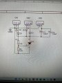
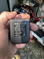
I have an old natural gas engine that I have designed a Capacitor Discharge Ignition module for. The module uses a pre-made boost circuit that takes 12vDC from a truck battery / solar cell and boosts it to 350vDC that I then route to my ignition circuit. This worked great on the bench where I used a plug in transformer 120vac to 12vDC that was rated at 0.1 Amps. When I hooked it to the battery I let the smoke out.
So I then clipped on an inverter, plugged my power supply in and everything worked great. This is NOT the way to do this. Can you please help me to make a 12vDC Source that controls the amperage available from the battery? I want something that won’t just drain the battery when not in use. I have a manual switch to turn on the 12vDC now so I could use that to kill power when not running but I also have a remote off switch that shuts off the gas valve. If the device keeps draining power that’s no good. I can use an interposing relay but I’d love to eventually love a more eloquent way to shut it off. Right now I’d settle for not roasting my boost circuit or using an inverter.
Thanks in advance.
 

Alec_t

Joined Sep 17, 2013
14,280
Welcome to AAC!
There's clearly a current surge which the battery can source but the boost circuit can't tolerate. Can you post a schematic (<300k file size) of your boost circuit?
 

Irving

Joined Jan 30, 2016
3,845
I don't understand why connecting it to the battery was a problem. The circuit should only take the current it needs and no more. Sounds like there's a issue with your circuit which relies on external current limiting to be safe. Post your schematic..
 

Thread Starter

MarkySparky42

Joined Aug 28, 2022
204
I don't understand why connecting it to the battery was a problem. The circuit should only take the current it needs and no more. Sounds like there's a issue with your circuit which relies on external current limiting to be safe. Post your schematic..
I agree. It should take what it needs. The limit is 5 Amps max.

Aobao 2pcs High Voltage DC-DC Boost Converter 8V-32V to 45V-390V ZVS Step-up Booster Module Capacitor Charging Power Supply Module Adjustable Voltage Output https://a.co/d/eCOfJ7B

I just don’t understand the “Why” part of why going through an inverter then my wall wart would make everything ok.


from Amazon:

High voltage DC-DC boost converter 8V-32V to ±45V-390V ZVS step-up booster module capacitor charging power supply module adjustable voltage output Specifications: Modular nature: Non-isolated boost module Input voltage: 8~32V input(the default is 10~32V input.) Input current: 5A (Max) Output voltage: +45~390V continuously adjustable (default output ±50V) Output current: 0.2A Max(with input, output pressure related,the higher the output voltage, output current is smaller) Output power: 40W (Peak 70W) Working temperature: -40 ~ + 85 degrees (ambient temperature is too high, please enhance heat dissipation) Operating frequency: 75 KHz Conversion efficiency: up to 88% (efficiency and input and output voltage, current, pressure-related) Quiescent current: 15mA (12V liter 50V, the output voltage, the higher the current will increase too quiet) Short circuit protection: Yes.(input 10A fuse, please do not directly short circuit and pull arc! Because it may damage the rectifier device, if you want to do this, please connect the series power resistor to limit current) Over current protection: Yes. (Input current exceeds 4.5A, reducing the output voltage) Over voltage protection: Yes. (Output voltage exceeds 410V, lowering the output voltage) Input reverse polarity protection: Yes (not self-recovery, reverse will burn the fuse, try not to reverse.) Installation: Four 3 mm screws Wiring method: terminal-free welding output (with housing for welding output) Size: 60 x 50 x 22mm Note: The module output is high voltage, on people, animals have life-threatening, the course please pay attention to safety precautions. Manual measurement, with small error. Please check size in detail before purchase. Real colors may slightly differ from the pictures, as it depends on specific monitor settings and light brightness. Package Included: 2 x Booster Mod
 

Thread Starter

MarkySparky42

Joined Aug 28, 2022
204
Welcome to AAC!
There's clearly a current surge which the battery can source but the boost circuit can't tolerate. Can you post a schematic (<300k file size) of your boost circuit?
no schematic - just a purchased part.
On the bench they are awesome little circuits.
 

Irving

Joined Jan 30, 2016
3,845
please do not directly short circuit and pull arc! Because it may damage the rectifier device, if you want to do this, please connect the series power resistor to limit current)
Well there's your answer! Drawing an arc pulls > 70W from HV supply, @ 80% efficiency that's >7A @ 12v... so on the PSU or inverter its limited to 5A, but the battery was happy to give it >7A and blow itself up!

In your opening post you said 'capacitor discharge ignition' but this isn't anything like a CDI. A CDI would use the HV supply to charge a capacitor then discharge that into the plug, isolating the HV when it did so.
 

Thread Starter

MarkySparky42

Joined Aug 28, 2022
204
Well there's your answer! Drawing an arc pulls > 70W from HV supply, @ 80% efficiency that's >7A @ 12v... so on the PSU or inverter its limited to 5A, but the battery was happy to give it >7A and blow itself up!

In your opening post you said 'capacitor discharge ignition' but this isn't anything like a CDI. A CDI would use the HV supply to charge a capacitor then discharge that into the plug, isolating the HV when it did so.
After I get this 12 V to 350 V DC created high then run it into the high voltage source of a CDI. It’s a very simple CDI with an SCR and a couple diodes And a voltage divider for the trigger Which comes from a small coil and a magnet on the engine.

The magneto is dead on this old oil well engine. It’s a Fairbanks-Morse 208, 12 hp hit and miss engine. The retrofitted magneto and CDI module cost about $500 so I said forget that I’m making my own.
 

Thread Starter

MarkySparky42

Joined Aug 28, 2022
204
I was thinking about purchasing a 12 V volt to regulator from the auto parts store that is limited to 4 A and put that before my 12 V to 350 V boost circuit
 

Alec_t

Joined Sep 17, 2013
14,280
I just don’t understand the “Why” part of why going through an inverter then my wall wart would make everything ok.
Presumably because one or other of those is limiting the current to a good bit less than 5A. Your plug-in transformer (wall-wart) is rated for only 120V*0.1A =12W input and 12V*0.1A =1.2W output.
 
Last edited:

Thread Starter

MarkySparky42

Joined Aug 28, 2022
204
Presumably because one or other of those is limiting the current to a good bit less than 5A. Your plug-in transformer (wall-wart) is rated for only 120V*0.1A =12W.
I want to take the inverter and plug-in transformer out of the equation and just use something simpler. I was looking at an automotive voltage regulator that will give me a steady 12 V DC out and current limit me to 4 A
 

Alec_t

Joined Sep 17, 2013
14,280
Would you trust a product whose spec (per that link) includes "Color: 12V Surge Protector " ?
I'm not sure that linked item has the current-limiting you need. The ad says it has overcurrent protection (but doesn't mention the limit value), then goes on to say "The load connected to the output end of the power regulator should not be more than MAX LISTED LOAD POWER, any higher rated load will cause damage to the power regulator."
It also says "Can not used long time by the MAX. LISTED LOAD POWER ", so may not be suitable if your setup is intended to be running continuously.
I have designed a Capacitor Discharge Ignition module
What is the maximum supply current this draws?
 

Thread Starter

MarkySparky42

Joined Aug 28, 2022
204
Would you trust a product whose spec (per that link) includes "Color: 12V Surge Protector " ?
I'm not sure that linked item has the current-limiting you need. The ad says it has overcurrent protection (but doesn't mention the limit value), then goes on to say "The load connected to the output end of the power regulator should not be more than MAX LISTED LOAD POWER, any higher rated load will cause damage to the power regulator."
It also says "Can not used long time by the MAX. LISTED LOAD POWER ", so may not be suitable if your setup is intended to be running continuously.

What is the maximum supply current this draws?
I agree

that’s why I’m hoping hear suggestions from you all.
 
Top