NPN/PNP circuit

Thread Starter

mas928s4

Joined Aug 14, 2014
5
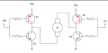
I have this transistor schematic that has me scratching my head. I was wondering if there is somebody out there that can explain it to me. I know the basics of how a PNP and NPN transistor works but this configuration to me looks like a glorified switch? Also is the circled "A" an ammeter? and shouldn't it be a motor?

Thank you,
 

Attachments

Jony130

Joined Feb 17, 2009
5,488
This is really bad design circuit. PNP transistor will work in "Inverted/reversed" region.
You should swap the emitter with collector.
And "A" for Armature.
 

Thread Starter

mas928s4

Joined Aug 14, 2014
5
Thank you for the link shteii. In all my years in field service I never ran across this configuration. I appreciate your quick response to my question,

Have a great day
 

Thread Starter

mas928s4

Joined Aug 14, 2014
5
Hi Jony130,

The wikilink explained the theory behind the design (H Bridge) pretty well as far as reversing the polarity of a motor which fits well with robotics. I agree the design isn't the greatest but is all I have to work with at the moment.
 

studiot

Joined Nov 9, 2007
4,998
Last edited:

Jony130

Joined Feb 17, 2009
5,488
Hi Jony130,

The wikilink explained the theory behind the design (H Bridge) pretty well as far as reversing the polarity of a motor which fits well with robotics. I agree the design isn't the greatest but is all I have to work with at the moment.
Hey what can I say. Try goggle "reverse active region".
And the "correct" diagram should look like this
http://forum.allaboutcircuits.com/attachment.php?attachmentid=71746&stc=1&d=1408034727

And here you have a idiot-proof h-bridge
 

Attachments

Thread Starter

mas928s4

Joined Aug 14, 2014
5
I'm not being critical as a matter of fact I am most appreciative of everyones input on this. To me its all good and useful information.
 
Top